Inst ToolsInst ToolsInst Tools
  • Courses
  • Automation
    • PLC
    • Control System
    • Safety System
    • Communication
    • Fire & Gas System
  • Instrumentation
    • Design
    • Pressure
    • Temperature
    • Flow
    • Level
    • Vibration
    • Analyzer
    • Control Valve
    • Switch
    • Calibration
    • Erection & Commissioning
  • Interview
    • Instrumentation
    • Electrical
    • Electronics
    • Practical
  • Q&A
    • Instrumentation
    • Control System
    • Electrical
    • Electronics
    • Analog Electronics
    • Digital Electronics
    • Power Electronics
    • Microprocessor
  • Request
Search
  • Books
  • Software
  • Projects
  • Process
  • Tools
  • Basics
  • Formula
  • Power Plant
  • Root Cause Analysis
  • Electrical Basics
  • Animation
  • Standards
  • 4-20 mA Course
  • Siemens PLC Course
Reading: Transistor Cut off, Saturation & Active Regions
Share
Font ResizerAa
Inst ToolsInst Tools
Font ResizerAa
  • Courses
  • Design
  • PLC
  • Interview
  • Control System
Search
  • Courses
  • Automation
    • PLC
    • Control System
    • Safety System
    • Communication
    • Fire & Gas System
  • Instrumentation
    • Design
    • Pressure
    • Temperature
    • Flow
    • Level
    • Vibration
    • Analyzer
    • Control Valve
    • Switch
    • Calibration
    • Erection & Commissioning
  • Interview
    • Instrumentation
    • Electrical
    • Electronics
    • Practical
  • Q&A
    • Instrumentation
    • Control System
    • Electrical
    • Electronics
    • Analog Electronics
    • Digital Electronics
    • Power Electronics
    • Microprocessor
  • Request
Follow US
All rights reserved. Reproduction in whole or in part without written permission is prohibited.
Inst Tools > Blog > Electronic Devices & Circuits > Transistor Cut off, Saturation & Active Regions

Transistor Cut off, Saturation & Active Regions

Last updated: September 27, 2016 2:38 pm
Editorial Staff
Electronic Devices & Circuits
2 Comments
Share
4 Min Read
SHARE

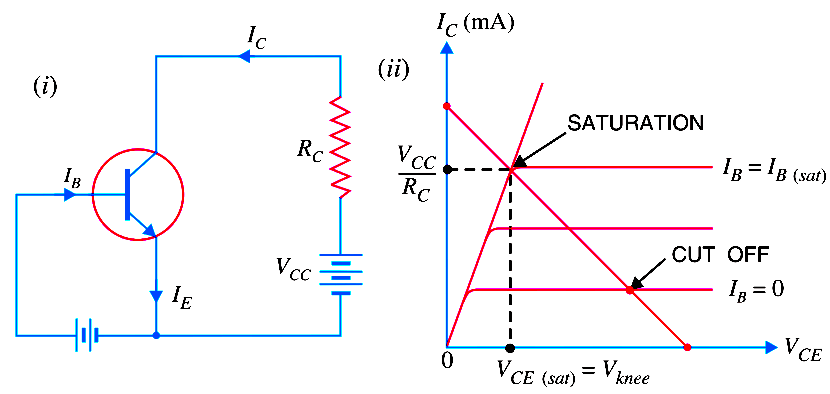
The below Fig. (i) shows CE transistor circuit while Fig.(ii) shows the output characteristcs along with the d.c. load line.

(i) Cut off. The point where the load line intersects the IB = 0 curve is known ascut off. At this point, IB = 0 and only small collector current (i.e. collector leakage current ICEO) exists. At cut off, the base-emitter junction no longer remains forward biased and normal transistor action is lost. The collector-emitter voltage is nearly equal to VCC i.e. VCE (cut off) = VCC
Transistor-cut-off-saturation-active-regions

(ii) Saturation. The point where the load line intersects the IB = IB(sat) curve is called saturation. At this point, the base current is maximum and so is the collector current. At saturation, collector-base junction no longer remains reverse biased and normal transistor action is lost.

Transistor-saturation-region-formula

If base current is greater than IB(sat), then collector current cannot increase because collector-base junction is no longer reverse-biased.

(iii) Active region. The region between cut off and saturation is known as active region. In the active region, collector-base junction remains reverse biased while base-emitter junction remains forward biased. Consequently, the transistor will function normally in this region.

Note. We provide biasing to the transistor to ensure that it operates in the active region. The reader may find the detailed discussion on transistor biasing in the next chapter.
transistor diode symbol

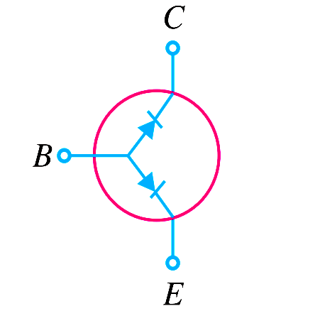
Summary. A transistor has two pn junctions i.e., it is like two diodes. The junction between base and emitter may be called emitter diode. The junction between base and collector may be called collector diode. We have seen above that transistor can act in one of the three states : cut-off, saturated and active.The state of a transistor is entirely determined by the states of the emitter diode and collector diode [See Above Fig]. The relations between the diode states and the transistor states are :

CUT-OFF : Emitter diode and collector diode are OFF.

ACTIVE : Emitter diode is ON and collector diode is OFF.

SATURATED : Emitter diode and collector diode are ON.

In the active state, collector current [See Below Fig (i)] is β times the base current (i.e. IC = IB). If the transistor is cut-off, there is no base current, so there is no collector or emitter current. That is collector emitter pathway is open [See Below Fig.]

(ii)]. In saturation, the collector and emitter are, in effect, shorted together. That is the transistor behaves as though a switch has been closed between the collector and emitter [See Below Fig. (iii)].

Transistor-regions

Note. When the transistor is in the active state, IC = IB. Therefore, a transistor acts as an amplifier when operating in the active state. Amplification means linear amplification. In fact, small signal amplifiers are the most common linear devices.
Don't Miss Our Updates
Be the first to get exclusive content straight to your email.
We promise not to spam you. You can unsubscribe at any time.
Invalid email address
You've successfully subscribed !

Continue Reading

Power MOSFET Safe Operating Area
Cathode Ray Tube Deflection System
Combining Independent Current Sources in Parallel
Limitations of Resistors
Choke Input Filter Operation
Permanent Magnet Moving Coil Instruments (PMMC)
Share This Article
Facebook Whatsapp Whatsapp LinkedIn Copy Link
Share
2 Comments
  • Chethan S says:
    December 17, 2021 at 5:41 am

    A small correction, in the note point at last. In the active region Ic=Beta times Ib. Please rectify this.

    Reply
    • Sam Quentin says:
      September 3, 2023 at 10:47 am

      Was curious about that.
      Thanks for the clarification.

      Reply

Leave a Reply Cancel reply

Your email address will not be published. Required fields are marked *

Stay Connected

128.3kFollowersLike
69.1kFollowersFollow
210kSubscribersSubscribe
38kFollowersFollow

Categories

Explore More

Optoisolator Working Principle
Tunnel Diode Working Principle
Circuit Elements and Types of Circuits
Series and Parallel Resistors
Half Wave Voltage Doubler using Diodes
CRT Fluorescent Screen
Semiconductors Diodes Questions & Answers
Why Silicon is preferred over Germanium ?

Keep Learning

Transistor Collector Characteristic Curves

Transistor Collector Characteristic Curves

Combining Independent Voltage Sources in Series

Combining Independent Voltage Sources in Series

MOSFET VI Characteristics

Power MOSFET

How a Multi Color LED Works

How a Multi Color LED Works ?

reverse-biased varactor diode

Varactor Diode Operation

Electron Gun of CRT

Electron Gun of Cathode Ray Tube

Diode-testing-with-multimeter

How to Test a Diode using Multimeter

pn-junction-with-depletion-layer

How a PN Junction Formed in a Diode

Learn More

Distributed Control Systems (DCS)

What is DCS? (Distributed Control System)

Pipeline Pig Detector

What are Non-Intrusive Pig Signallers or Pig Detectors?

Digital Electronics Multiple Choice Questions

Multiplexers Objective Questions – Part 2

liquid flow control system

Practical Process Control System Questions & Answers – 7

Impulse Line Pressure Testing Procedure

Impulse Line Pressure Testing Procedure

feedforward control theory

Proportioning Feedforward action

WirelessHART Network Protocol

WirelessHART Network Protocol

Siemens PLC Programming OBs in Siemens TIA Portal

FC Function in Siemens PLC

Menu

  • About
  • Privacy Policy
  • Copyright

Quick Links

  • Learn PLC
  • Helping Hand
  • Part Time Job

YouTube Subscribe

Follow US
All rights reserved. Reproduction in whole or in part without written permission is prohibited.
Welcome Back!

Sign in to your account

Username or Email Address
Password

Lost your password?