Electrical Drives are drives that employ the control of motion of electric motors. Motion control is required in a large number of industrial and domestic applications.
Modes of Electrical Drives
These electrical drives usually operate in mainly three modes.
They are:
- Steady State
- Acceleration including starting
- Deceleration including stopping
Steady State Operation
Steady State operation takes place when motor torque equals the load torque. The steady-state operation for a given speed is realized by the adjustment of steady-state motor speed and torque such that motor and load torques are equal at this speed.
Change in speed is achieved by varying the steady-state motor speed and torque so that motor torque equals the load torque at the new speed. Steady-state operations can also be obtained by adding a mechanical brake which will produce a torque in a direction to oppose the motion.
The steady-state operation is obtained at a speed for which braking torque equals the load torque. Since mechanical braking is used for opposing the motion, it has some disadvantages like frequent maintenance, replacement of brake shoes, lower life, and braking power is always wasted as heat.
These advantages are overcome by the use of electrical braking in which the motor will be work as a generator which converts mechanical energy to electrical energy and produces torque in a direction so as to oppose the motion. Even when electrical braking is fixed, mechanical brakes are also provided to ensure reliable operation of the drive.
Acceleration State
Acceleration and deceleration modes are transient operations. The drive operates in acceleration mode whenever an increase in its speed is required.
For this motor speed and torque must be changed so that the motor exceeds the load torque. The time taken for a given change in speed depends on the inertia of the motor-load system and the amount by which motor torque exceeds the load torque.
An increase in motor is accompanied by an increase in motor current. In applications involving acceleration periods of long duration, current must not be allowed to exceed the rated value. When acceleration periods are of short duration a current higher than the rated value is allowed during acceleration.
In closed-loop drives requiring fast response, motor current may be intentionally forced to the maximum value in order to achieve high acceleration. Torque which was developed on the motor for a given current is usually a function of the motor control method employed. In high-performance drives, methods that produce high torque per ampere of motor current.
Deceleration State
Motor operation in deceleration mode is required when a decrease in its speed is required. Deceleration occurs when load torque exceeds the motor torque.
In those applications where load torque is always present with substantial magnitude, enough deceleration can be achieved by simply reducing the motor torque to zero.
In those applications where load torque may not always have a substantial amount or where simply reducing the motor torque to zero does not provide enough deceleration, mechanical brakes may be used to produce the required magnitude of deceleration.
Alternatively, electric braking may be employed. Now both motor and load torque oppose the motion, thus producing larger deceleration. During electric braking, motor current tends to exceed the safe limit. Appropriate changes are made to ensure that the current is restricted within safe limits.
When electric braking may persist for long periods, the maximum current is usually restricted to the rated value. When electric braking occurs for shot durations, the maximum current is allowed to exceed the rated value. The higher the breaking torque greater the deceleration.
Speed Control of Drives
Drives, where the driving motor runs at a nearly fixed speed, are known as constant-speed or single-speed drives.
Multi-speed drives are those which operate at discrete speed settings. Drives needing stepless change in speed and multispeed drives are called Variable Speed Drives. When a number of motors are fed from a single converter or when a load is driven by more than one motor then the drive is known as multi-motor drive.
A variable speed drive is called a constant torque drive if the drive’s maximum torque capability does not change with a change in speed setting. The corresponding mode of operation is called constant torque mode.
Constant torque refers to the maximum torque capability of the drive and not to the actual output torque, which will vary from no load torque to full load torque. The motor speed should remain constant as load torque is changed from no load to full load.
Normally, Speed will drop with an increase in the load torque. Speed regulation of the drive was calculated by,
Speed Regulation = [(No load Speed – Full load Speed) / Full Load Speed ] * 100
Speed Regulation was possible in both open loop and Control loop systems. Normally open loop system is used, if is fails to provide the desired speed regulation, the drive is operated as a closed-loop speed control system.
Closed Loop Control of Drives
Feedback loops in an electrical drive were applied on the application when the open loop failed to give the desired speed and also closed loop control system will provide the following advantages. They are Protection, enhancement of speed of response, and improvement of steady state accuracy.
Types of Closed-Loop Drives
This Closed-loop control has four types for controlling the drives in an efficient way.
They are:
- Current- Limit Control
- Closed Loop Torque control
- Closed Loop speed control
- Closed Loop Position Control
Current Limit Control
Current limit control is used to limit the converter and motor current below a safe limit during transient operations. It has a current feedback loop with a threshold circuit on it.
As long as the current is within a set maximum value, the feedback loop does not affect the operation of the drive. During a transient operation, if the current exceeds the set maximum value, the feedback loop becomes active, and the current is forced below the set maximum value, which makes the feedback to inactive again.
If the current exceeds the set maximum value again, it is again brought below it by the action of the feedback loop. Thus the current fluctuates around a set maximum limit during the transient operation until the drive condition is such that the current does not have a tendency to cross the maximum set value.
For example, during starting, the operation current will always fluctuate around the maximum value. When close to the steady-state operation point, the current will not have tendency to cross the maximum value so that in this feedback loop will have no effect on the drive operation.
Closed Loop Torque Control
Closed-loop torque control is mainly used in the applications of battery-operated vehicles, rail cars, and electric trains. In this, Reference torque is set, through closed-loop control of torque, and the actual motor torque follows the reference torque.
The speed feedback loop is present through the drive controller. By putting the appropriate pressure on the accelerator, the speed will be adjusted depending on the condition. In this, depending on the reference torque, the loop executes and does the process.
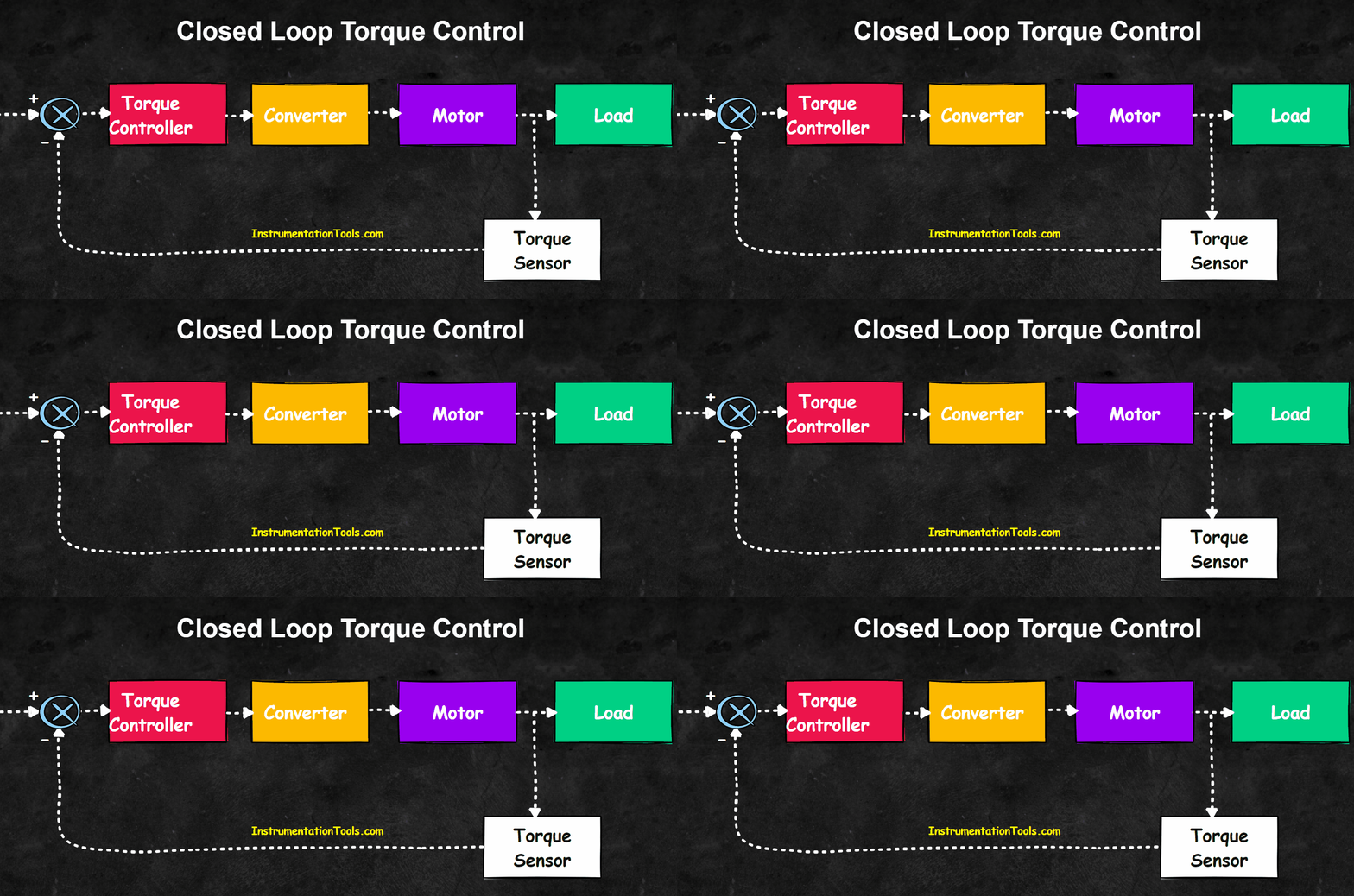
Closed Loop Torque Control
Closed-Loop Speed control
Closed-loop speed control employs an inner control loop within an outer-speed loop. An inner current loop is provided to limit the converter and motor current at a safe limit.
In some schemes, the current is controlled directly and in some categories, the current is controlled indirectly. In this, the drive performance of any non-linearity present in the converter-motor system was reduced by the effect of the Inner current loop.
An increase in reference speed will produce a positive error. Error speed is processed through a speed controller and applied to a current limiter which saturates even for a small speed error.
Similarly, a decrease in reference speed will produce a negative error. The current limiter saturates and sets the current reference for an inner current loop at a value corresponding to the maximum allowable current. When close to the required speed, the current limiter desaturates.
Then the operation is transferred from braking to motoring. Drive then settles at a desired speed and at the current for which motor torque equals the load torque.
In those drives where the current does not have to reverse for braking operation. In those applications where the load torque is able to provide enough decelerating torque, electric braking need not be used.
Closed Loop Position Control
A closed-loop position control system consists of a closed-loop speed control system with an inner current control loop inside an outermost position loop.
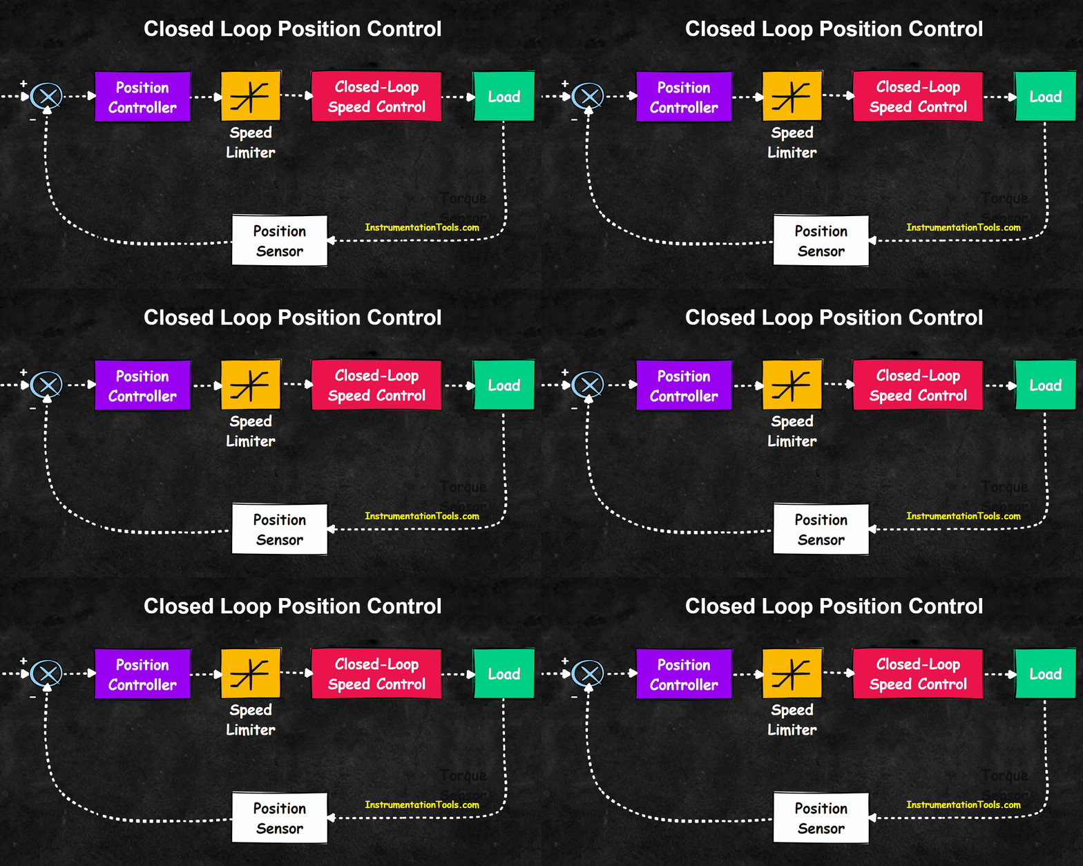
Current and speed loops restrict the current and speed within the safe limits, enhance the speed of response, and reduce the effects of non-linearities in the converter, motor, and load on the transient and steady-state performance of the position control system. Position controls are required in a number of drive applications.
These controls are mostly used in machine tools and screw-down mechanisms in rolling mills.
If you liked this article, then please subscribe to our YouTube Channel for Electrical, Electronics, Instrumentation, PLC, and SCADA video tutorials.
You can also follow us on Facebook and Twitter to receive daily updates.
Read Next:
- What is an Electrical Conduit?
- Single Core and Multi-Core Cables
- Difference Between HV and LV Cables
- Types of Cables in Industrial Automation
- Flame Resistant and Retardant Cables
