Motors are a very important part of electrical engineering and industrial automation. A motor will convert electrical energy into mechanical energy, and mechanical energy is required mostly everywhere for moving a thing. So, the motor is of very important use. We have commonly heard of standard AC and DC motors, but one more type of motor is used in many industrial automation applications. This is a stepper motor.
A stepper motor is widely used due to its precision, accuracy, and reliability. There are many types of stepper motors available and it is important to understand their meaning. In this post, we will see the various types of stepper motors.
What is a Stepper Motor?
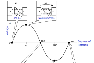
First, let us understand the basic concept of a motor. When a permanent magnet is placed around an electric field, an electromagnetic field is generated and the force of this field causes attraction and repulsion, which causes the magnet to move around it – clockwise or anti-clockwise. This theory extends to a stepper motor.
A stepper motor too will convert this electrical energy into mechanical energy, but as the name implies, it rotates in steps. This means you get control over a fixed amount of degrees. Compare it with a normal DC or AC motor, and you will see that there is no control over how much amount of degrees you want to rotate. The motor will rotate continuously at the desired speed.
But, in a stepper motor, you can control how much amount of degrees you want to rotate it. This makes it perfect for machine automation applications, where accuracy and precision are a must.
Working of Stepper Motor
Refer to the below image. You know that a motor has two parts – a stator (stationary part) and a rotor (rotating part). The stator winding here has teeth on which the electric wire is coiled. The rotor winding (magnet) is placed in between the stator.
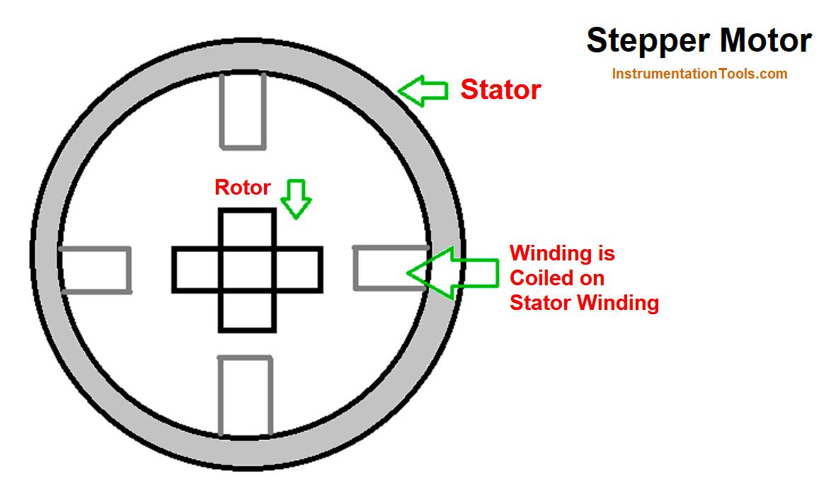
Now, as per the theory discussed earlier, when an electric current is passed, the magnet will align itself toward it. In the above image, the current is given in such a way that two opposite phases are placed in the exact opposite.
This means the vertical alignment can have A+ and A-; whereas the horizontal alignment can have B+ and B-. So, when current is given in one phase, the magnet will be aligned towards it.
In the next phase, the magnet will move towards that alignment and place it in line with that. This way, as the phase current is changed, the magnet will rotate along with it (to align itself with the stator current one) and thus make a moving part.
Here, you can see that the magnet will move only when the current in a stator winding is applied one at a time. Where the current is, the magnet is aligned there. So, here, you have entire control of the rotation. It’s in your hand when to apply the current and in which phase.
Now, you will be thinking about how the current is controlled. Then, in this age of semiconductors, it is easily possible to control when to apply current and when not, by the use of controllers (like PLC or microcontrollers) and phase controller. The fast on-off of phase is current and smooth switching helps determine which winding must be applied current.
Types of Stepper Motors
Some of the popular stepper motors are listed below
- Permanent Magnet Stepper Motor
- Variable Reluctance Stepper Motor
- Hybrid Stepper Motor
Permanent Magnet Type Stepper Motor
This is the very basic type of stepper motor. Remember that the type of stepper motor indirectly means the type of rotor used in it. In this type, a permanent magnet is used in the rotor. As the name implies, the magnetic field of this magnet is maintained permanently. It is similar to a compass. It is circular in shape, half size being North Pole and half size being South Pole.
Due to its construction and properties, the magnetic field is continuously present in the whole element. Getting back to our earlier discussion, when the electric current is applied to a stator winding, the magnet in this case will move according to it and align itself in line with the stator current.
But, due to its circular design, the resolution of the permanent magnet stepper motor is lower than the other types; though you get the best amount of torque in this motor. Less resolution means you have fewer options for getting the desired angles. The movement will be mostly 45 degrees or 90 degrees.
Variable Reluctance Stepper Motor
As the name implies, reluctance means hesitation. So, in stepper motor terms, the rotor’s magnetic field is assigned in such a way that it will offer minimum reluctance with the stator windings. The gap will be very less between them, meaning the rotor is almost symmetrical with the rotor.
This example can be better understood with the diagram shown above. But, the difference is that only one pole will remain aligned with the stator at a time. Due to this, you have a better angle resolution in this motor compared to a permanent magnet motor; because for supporting this type, more teeth and windings will be provided; thus providing more angular control. So, the position of the rotor finally depends on how reluctant it is to align itself with the stator winding.
Hybrid Stepper Motor
It is a combination of both the permanent magnet and variable reluctance motor. You get a larger amount of permanent magnetic field in the rotor as compared to the variable reluctance type; but at the same time, only some poles will be aligned with the stator.
This allows the highest number of resolutions in all types. You get more options for the number of teeth and windings in this type. When you require minute step movements, then this motor is the best to use.
If you liked this article, then please subscribe to our YouTube Channel for Electrical, Electronics, Instrumentation, PLC, and SCADA video tutorials.
You can also follow us on Facebook and Twitter to receive daily updates.
Read Next:
- Electrical Drawings
- Motor Cooling Methods
- SCADA in Power System
- What is a Buchholz Relay?
- Cables between VFD & Motor