Inst ToolsInst ToolsInst Tools
  • Courses
  • Automation
    • PLC
    • Control System
    • Safety System
    • Communication
    • Fire & Gas System
  • Instrumentation
    • Design
    • Pressure
    • Temperature
    • Flow
    • Level
    • Vibration
    • Analyzer
    • Control Valve
    • Switch
    • Calibration
    • Erection & Commissioning
  • Interview
    • Instrumentation
    • Electrical
    • Electronics
    • Practical
  • Q&A
    • Instrumentation
    • Control System
    • Electrical
    • Electronics
    • Analog Electronics
    • Digital Electronics
    • Power Electronics
    • Microprocessor
  • Request
Search
  • Books
  • Software
  • Projects
  • Process
  • Tools
  • Basics
  • Formula
  • Power Plant
  • Root Cause Analysis
  • Electrical Basics
  • Animation
  • Standards
  • 4-20 mA Course
  • Siemens PLC Course
Reading: Drilling Process using PLC Program
Share
Font ResizerAa
Inst ToolsInst Tools
Font ResizerAa
  • Courses
  • Design
  • PLC
  • Interview
  • Control System
Search
  • Courses
  • Automation
    • PLC
    • Control System
    • Safety System
    • Communication
    • Fire & Gas System
  • Instrumentation
    • Design
    • Pressure
    • Temperature
    • Flow
    • Level
    • Vibration
    • Analyzer
    • Control Valve
    • Switch
    • Calibration
    • Erection & Commissioning
  • Interview
    • Instrumentation
    • Electrical
    • Electronics
    • Practical
  • Q&A
    • Instrumentation
    • Control System
    • Electrical
    • Electronics
    • Analog Electronics
    • Digital Electronics
    • Power Electronics
    • Microprocessor
  • Request
Follow US
All rights reserved. Reproduction in whole or in part without written permission is prohibited.
Inst Tools > Blog > PLC Tutorials > Drilling Process using PLC Program

Drilling Process using PLC Program

Last updated: March 4, 2021 3:46 pm
Editorial Staff
PLC Tutorials
1 Comment
Share
2 Min Read
SHARE

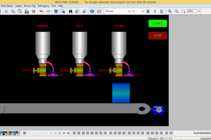
Drilling process is one the example Program in PLC using RSLOGIX 500.

Contents
PLC Drilling MachineStep Conditions:Input/OutputPLC Drilling programLogic DescriptionConclusion:

PLC Drilling Machine

PLC based drilling machine

Step Conditions:

  1. Start PB is to start the process.
  2. At initial, Job in sensor, Drill up sensor should be in ON condition and job out sensor should be in OFF condition.
  3. When job in sensor detects object for drilling should turn on conveyor motor to move the object.
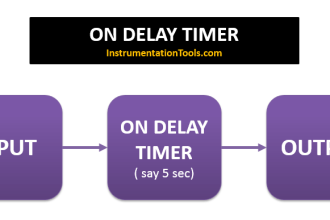
  4. When Position sensor detects object, conveyor motor should turn OFF and after 5 sec Drill forward Motor should ON until drill down sensor ON. After Delay of 5sec, Drill reverse motor should ON up to Drill up sensor ON.
  5. After 5 sec delay, Conveyor motor runs till job out sensor ON.
  6. Program run continuously till stop PB pressed.

Input/Output

PLC input output drilling machine

PLC Drilling program

Drilling Process using PLC Program
PLC Drilling Machine Logic

Logic Description

RUNG000

Latching rung to operate the system through Master Start and Stop PB.

RUNG001

To save the status of Job in sensor, Drill Up sensor and Job Out sensor, Memory coil is used.

RUNG 0002

when all the sensors are in Home condition, Conveyor Motor turned ON

Rung 0003 – RUNG 0004

Position sensor ON makes a time delay of 5 sec to turn  Drill forward ON up to drill reverse ON

Rung 0005 – RUNG 0006

Drill down sensor ON makes a time delay of 5 sec to turn  Drill reverse ON till drill up sensor ON

Rung 0007

After 5 sec delay, Conveyor motor runs up to job out sensor ON condition.

Program runs continuously until STOP PB is pressed.

Conclusion:

The above explained Drilling process is for example only. Real time may vary in different logic.

Author : Hema Sundaresan

If you liked this article, then please subscribe to our YouTube Channel for PLC and SCADA video tutorials.

You can also follow us on Facebook and Twitter to receive daily updates.

Read Next:

PLC Motor Operation

PLC Speed Control

4 Way Traffic Light Control

PLC Bell Control Logic

Flip Flop PLC Ladder Diagram

Don't Miss Our Updates
Be the first to get exclusive content straight to your email.
We promise not to spam you. You can unsubscribe at any time.
Invalid email address
You've successfully subscribed !

Continue Reading

How to Check Address Overlapping in Tia Portal?
PLC Program for Washing Machine
Example of Flip-Flop PLC Program for Lamps Application
Working Principle of Single Phase Preventer Relay
Communication between Wincc and Tia Portal
What is Midline Instruction in Siemens PLC?
Share This Article
Facebook Whatsapp Whatsapp LinkedIn Copy Link
Share
1 Comment
  • Aladin jlassi says:
    May 25, 2025 at 3:03 pm

    hi , I think there is an error in line 7 of the program please check it .

    Reply

Leave a Reply Cancel reply

Your email address will not be published. Required fields are marked *

Stay Connected

128.3kFollowersLike
69.1kFollowersFollow
210kSubscribersSubscribe
38kFollowersFollow

Categories

Explore More

Demo of a SCADA Software – Level Control System
Best Way to Build Troubleshooting Mindset for Automation Engineer
PLC Programming Example for Motor Forward and Reverse Control
Sequential Operation of Output Bits using Two Push buttons
Multiple Pumps Control using PLC
What is PLC Redundancy?
How to implement SR Flip Flop using PLC Ladder Logic
PLC Problems Troubleshooting

Keep Learning

One-Shot Rising and Falling Edge Instructions in Rockwell PLC

One-Shot Rising and Falling Edge Instructions in Rockwell PLC

HMI screen for operator

Auto Tiffin Box Filling Station

Pre-Engineering Design Documents

Industrial Automation Pre-Engineering Design Documents – Project & Process

Masked Move Instructions

How to use Masked Move Instruction in PLC

PLC engineering software

How to Download GX Works? Mitsubishi PLC Software

Electrical and Instrumentation Engineering Documents

Electrical and Instrumentation – Automation Pre-engineering Documents

Instrument Junction Box

Instrumentation System Architecture

What is meant by the Batching Process

Batch Simulator PLC Example Program using LogixPro Simulator

Learn More

Proportional Controller Response Curve

Proportional Controller Principle

Miniature Circuit Breakers Questions and Answers

Miniature Circuit Breakers Questions and Answers

Control valve sizing

Basics of Control Valve Sizing

PLC ON DELAY TIMER FUNCTION

#6 PLC Best Practices – Validate Timers and Counters

Magnetic Flow Meter Liner Damaged

Magnetic Flow Meter Liner Damaged and Winding Burnt

Things You Need to Know About DeviceNet

Things You Need to Know About DeviceNet

Power Electronics Objective Questions

Power Electronics Filters Questions and Answers

Questions on Pneumatic Control Loop

Questions on Pneumatic Control Loop

Menu

  • About
  • Privacy Policy
  • Copyright

Quick Links

  • Learn PLC
  • Helping Hand
  • Part Time Job

YouTube Subscribe

Follow US
All rights reserved. Reproduction in whole or in part without written permission is prohibited.
Welcome Back!

Sign in to your account

Username or Email Address
Password

Lost your password?