Inst ToolsInst ToolsInst Tools
  • Courses
  • Automation
    • PLC
    • Control System
    • Safety System
    • Communication
    • Fire & Gas System
  • Instrumentation
    • Design
    • Pressure
    • Temperature
    • Flow
    • Level
    • Vibration
    • Analyzer
    • Control Valve
    • Switch
    • Calibration
    • Erection & Commissioning
  • Interview
    • Instrumentation
    • Electrical
    • Electronics
    • Practical
  • Q&A
    • Instrumentation
    • Control System
    • Electrical
    • Electronics
    • Analog Electronics
    • Digital Electronics
    • Power Electronics
    • Microprocessor
  • Request
Search
  • Books
  • Software
  • Projects
  • Process
  • Tools
  • Basics
  • Formula
  • Power Plant
  • Root Cause Analysis
  • Electrical Basics
  • Animation
  • Standards
  • 4-20 mA Course
  • Siemens PLC Course
Reading: Door Lock with Delay PLC Exercise Problems
Share
Font ResizerAa
Inst ToolsInst Tools
Font ResizerAa
  • Courses
  • Design
  • PLC
  • Interview
  • Control System
Search
  • Courses
  • Automation
    • PLC
    • Control System
    • Safety System
    • Communication
    • Fire & Gas System
  • Instrumentation
    • Design
    • Pressure
    • Temperature
    • Flow
    • Level
    • Vibration
    • Analyzer
    • Control Valve
    • Switch
    • Calibration
    • Erection & Commissioning
  • Interview
    • Instrumentation
    • Electrical
    • Electronics
    • Practical
  • Q&A
    • Instrumentation
    • Control System
    • Electrical
    • Electronics
    • Analog Electronics
    • Digital Electronics
    • Power Electronics
    • Microprocessor
  • Request
Follow US
All rights reserved. Reproduction in whole or in part without written permission is prohibited.
Inst Tools > Blog > PLC Tutorials > Door Lock with Delay PLC Exercise Problems

Door Lock with Delay PLC Exercise Problems

Design a control system for automatic door lock with delay using PLC programming and motion sensor.

Last updated: April 22, 2024 1:43 pm
Editorial Staff
PLC Tutorials
No Comments
Share
5 Min Read
SHARE

Design a control system for automatic door lock with delay using PLC programming.

Contents
Door Lock with DelayPLC Exercise ProblemsInputs & OutputsLogic SolutionProgram ExplainedWhen Sensor gets activated or Sensor detects someone approachingWhen Sensor deactivates or (When sensor does not detect anyone for 5 seconds)

Note: This PLC program was created for the persons for learning the PLC programming with simple problems.

Door Lock with Delay

Problem Statement:

Design a PLC ladder logic for the following application.

We are using one Sensor to control the Door Lock.

The Motion Sensor detects when someone approaching the door should wait for 10 seconds and then open it. If no one is detected for 5 seconds, the door should close.

PLC Exercise Problems

This video explains the PLC programming for automatic door lock with delay logic.

PLC Programming Exercise - Automated Door with Delay

Inputs & Outputs

Digital Inputs:

Sensor: I0.0

Digital Outputs:

Door Lock: Q0.0

Logic Solution
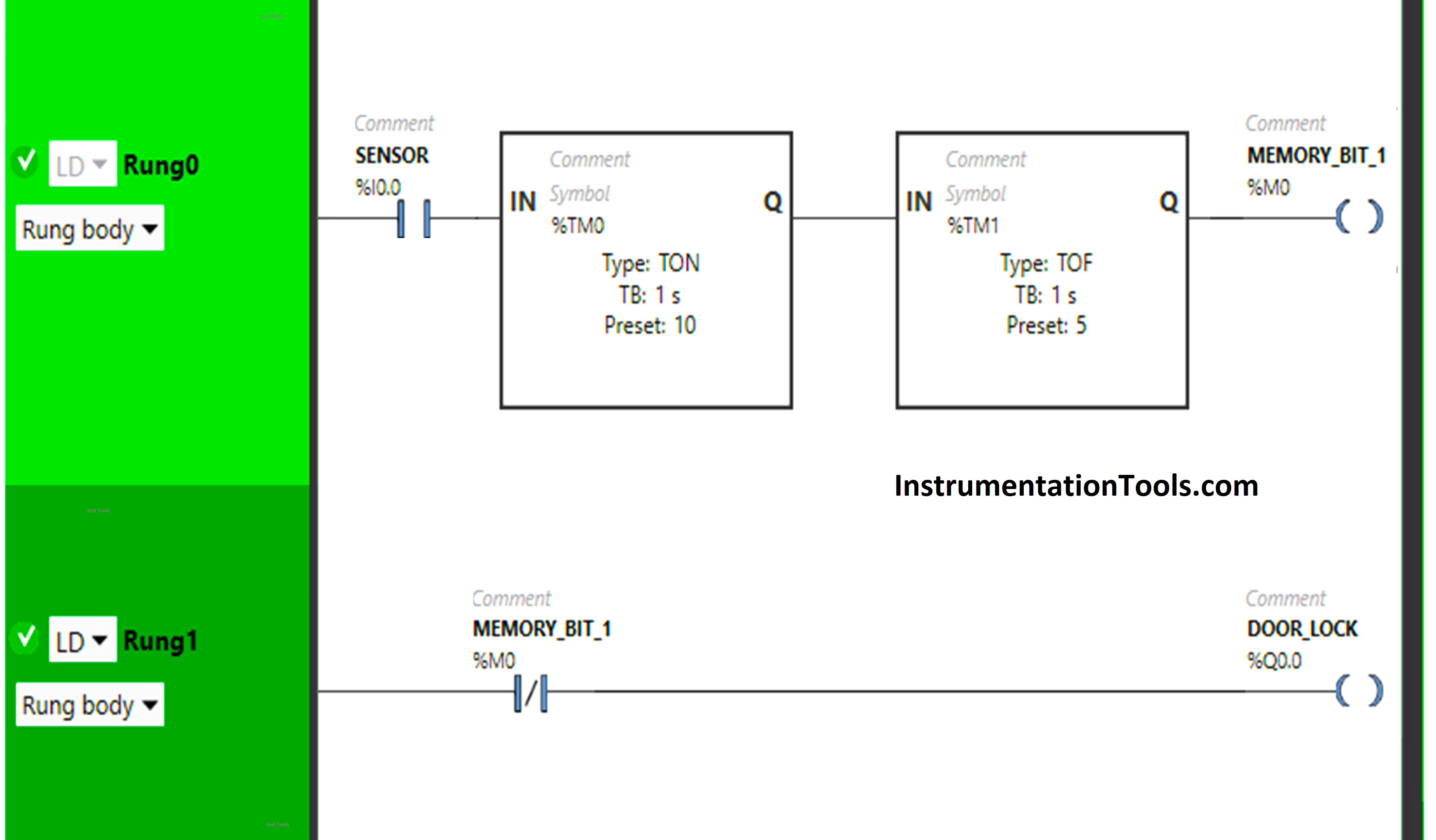
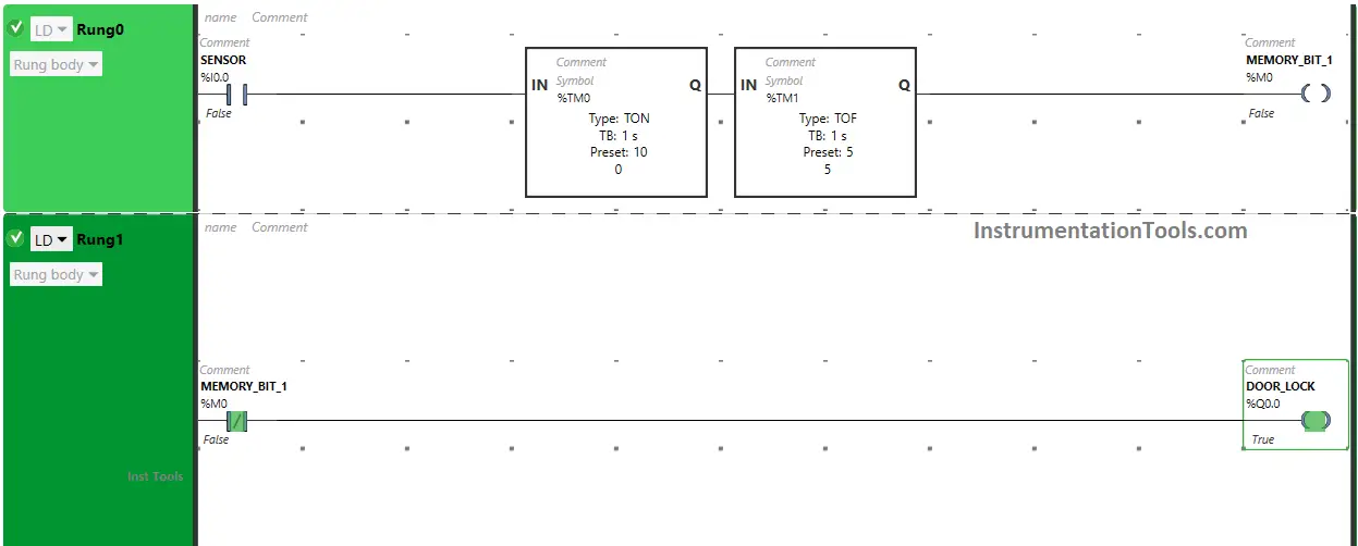
Door Lock with Delay PLC Exercise Problems

Program Explained

We have used Normally Open Contact for Sensor (I0.0).

We have used Normally Closed Contact for Memory Bit 1 (M0).

In Rung 0:

  1. Normally Open Contact is used for Sensor  (I0.0) to Turn ON Memory Bit 1 (M0).
  2. Timer type TON is used to delay the turning ON time of Memory Bit 1 (M0) for some time.
  3. Timer type TOF is used to delay the turning OFF time of Memory Bit 1 (M0) for some time.

In Rung 1:

  1. Normally Closed Contact is used for Memory Bit 1 (M0) to Turn ON and OFF the output Door Lock (Q0.0).

When Sensor  (I0.0) gets activated or (Sensor detects someone approaching), the Memory Bit 1 (M0) will turn ON after 10 seconds as Timer Function Block TON is used to delay the turning ON time of Memory Bit 1 (M0). The time is set to 10 seconds. After 10 seconds, Memory Bit 1 (M0) will turn ON.

When Memory Bit (M0) turns ON in Rung0, Normally Closed Contact used for Memory Bit 1 (M0) in Rung1 will be True state and does not allow the signal to pass through it and the output Door Lock (Q0.0) will turn OFF or (Doors will Unlock).

When Sensor (I0.0) deactivates or ( Sensor does not detect anyone approaching), Memory Bit 1 (M0) will turn OFF after 5 seconds as Timer Function Block type TOF is used to delay the turning OFF time of Memory Bit 1 (M0). The time is set to 5 seconds.

After 5 seconds, Memory Bit 1 (M0) will turn OFF. When Memory Bit 1 (M0) turns OFF in Rung0. Normally Closed Contact used for Memory Bit 1 (M0) in Rung1 will be false state and allow the signal to flow through it and the output Door Lock (Q0.0) will turn ON or (Doors will Lock).

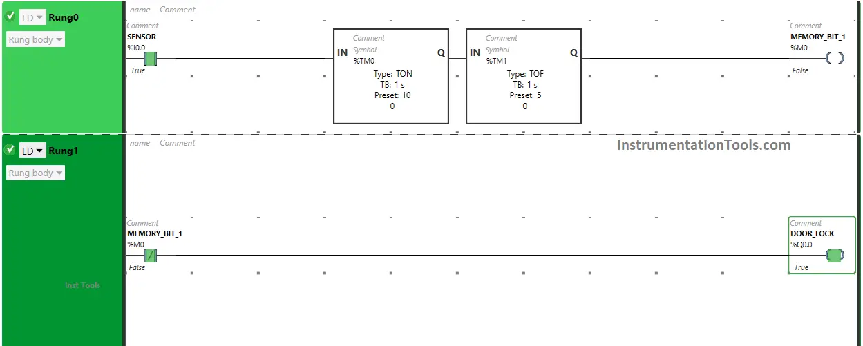
When Sensor gets activated or Sensor detects someone approaching

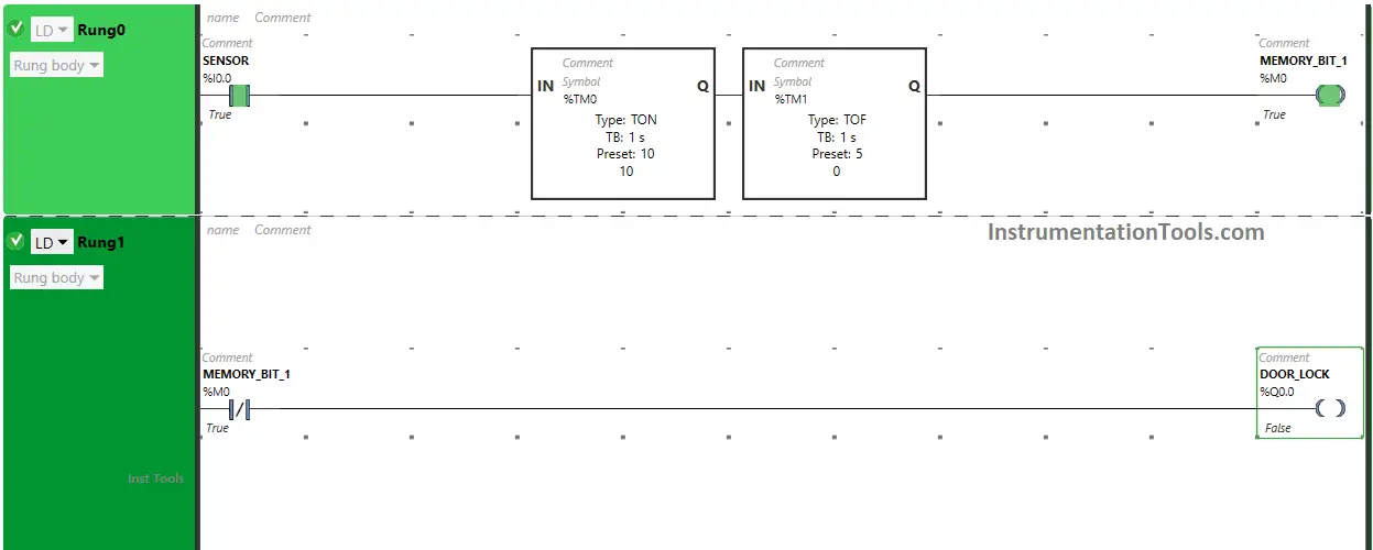
When Sensor (I0.0) gets activated or (Sensor detects someone approaching), the Memory Bit 1 (M0) will turn ON after 10 seconds as Timer Function Block TON is used to delay the turning ON time of Memory Bit 1 (M0). The time is set to 10 seconds.
Automated Door with Delay

After 10 seconds, Memory Bit 1 (M0) will turn ON. When Memory Bit (M0) turns ON in Rung0.

Normally Closed Contact used for Memory Bit 1 (M0) in Rung1 will be True state and does not allow the signal to pass through it and the output Door Lock (Q0.0) will turn OFF or ( Doors will Unlock).
Door Locking Ladder Logic

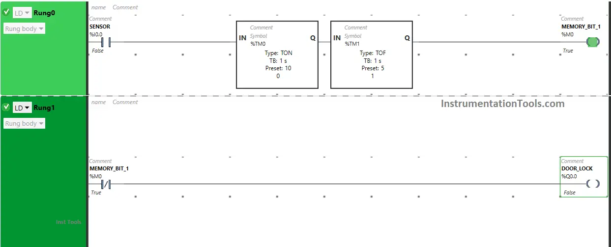
When Sensor deactivates or (When sensor does not detect anyone for 5 seconds)

When Sensor (I0.0) deactivates or ( Sensor does not detect anyone approaching), Memory Bit 1 (M0) will turn OFF after 5 seconds as Timer Function Block type TOF is used to delay the turning OFF time of Memory Bit 1 (M0). The time is set to 5 seconds.
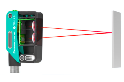
sensor can be programmed to open the door

After 5 seconds, Memory Bit 1 (M0) will turn OFF. When Memory Bit 1 (M0) turns OFF in Rung0.

Normally Closed Contact used for Memory Bit 1 (M0) in Rung1 will be false state and allow the signal to flow through it and the output Door Lock (Q0.0) will turn ON or (Doors will Lock).
Design of PLC Control System for Automatic Door

If you liked this article, please subscribe to our YouTube Channel for PLC and SCADA video tutorials.

You can also follow us on Facebook and Twitter to receive daily updates.

Read Next:

  • PLC Example Switch Program with Timers
  • Heater and Cooler PLC Exercise Problem
  • Automated Garage Gate PLC Programming
  • Pumping and Draining PLC Ladder Logic
  • Curtain Control PLC Programming Solution
Don't Miss Our Updates
Be the first to get exclusive content straight to your email.
We promise not to spam you. You can unsubscribe at any time.
Invalid email address
You've successfully subscribed !

Continue Reading

SCADA Multiple Choice Questions
DeMorgan’s Theorems using Ladder Diagram
PLC Program for Temperature Control using Thermostat
Various Causes for PLC Going in Stop Mode
Redundant Automation Systems – Need and Advantages
What is the Firmware Version of a PLC? – Siemens PLC Hardware
Share This Article
Facebook Whatsapp Whatsapp LinkedIn Copy Link
Share
Leave a Comment

Leave a Reply Cancel reply

Your email address will not be published. Required fields are marked *

Stay Connected

128.3kFollowersLike
69.1kFollowersFollow
210kSubscribersSubscribe
38kFollowersFollow

Categories

Explore More

System Cabinet Health Checks – PLC and DCS Industrial Automation
ControlLogix Architecture – Rockwell Automation
PID Controllers in Closed Loop Control Systems – PLC Basics
Function Block (FB) for Motor Control Logic
Top Free PLC Software
PLC 1 Push Button to Turn ON or OFF 1 Output
PLC Memory Organization – Data Files and Program Files
What are Analog Inputs? – Analog Signals Processing in PLC

Keep Learning

Count the Number of Bottles

Count the Number of Bottles in Packaging Carton PLC Logic

Online and Diagnostics of Siemens PLC

How to Use Diagnostic Buffer for SIEMENS PLC?

If Else Statement in SCL Language

If Else Statement in SCL Language

Omron PLC real-time clock street lighting program

Automatic Highway Lights Program using RTC in Omron PLC

Lights with Adjustable Timers PLC Programming

Flip-Flop PLC Programming: Lights with Adjustable Timers

FIFO in STL Language in Siemens PLC

How to Code a FIFO Queue in STL Language in Siemens PLC?

Difference Between Normal Counters and Fast Counters - PLC Basics

Difference Between Normal Counters and Fast Counters – Learn PLC

Omron PLC increment and decrement

Increment & Decrement Instructions in CX-Programmer (OMRON)

Learn More

Ultrasonic Level Switch Working Animation

Ultrasonic Level Switch Working Principle

Importance of Fire & Gas Detection System

Importance of Fire & Gas Detection System

AC generator Voltage Regulators

AC Generator Voltage Regulators

Brushed DC Motor Working Animation

Brushed DC Motor Working Animation

PLC Automatic Pedal Switch for Speed Control

PLC Automatic Pedal Switch for Speed Control

JFET Working Animation

JFET Working Animation

Free Safety Instrumented System Training Course

Free Safety Instrumented System Training Course

Accelerometer Vibration Probe

Accelerometer Vibration Probe Principle

Menu

  • About
  • Privacy Policy
  • Copyright

Quick Links

  • Learn PLC
  • Helping Hand
  • Part Time Job

YouTube Subscribe

Follow US
All rights reserved. Reproduction in whole or in part without written permission is prohibited.
Welcome Back!

Sign in to your account

Username or Email Address
Password

Lost your password?