Redundancy is a very important term in industrial automation. If you are working on a very critical process, and if you do not have a backup; then in the event of failure, your system will shut down and totally hamper the process.
If the process is too risky, then it can be life-threatening too. So, it is always necessary to have a backup for critical processes. When the primary system fails, a standby system in the backup will save the system from going down.
Redundancy means a system where a process works in two ways – primary and standby. Redundancy comes in three types – hot, cold, and warm.
In this post, we will learn the difference between hot standby and cold standby.
What is Cold Standby?
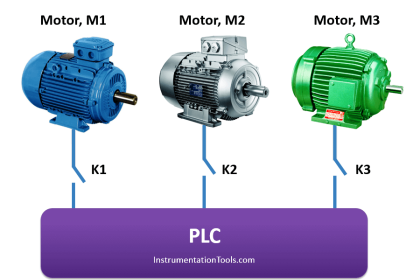
Suppose you have two PLCs. One PLC is working as a primary one. The same program running in primary PLC is present in standby PLC, but it is not powered on. Also, no communication cables have been connected to it. It can thus be considered as a spare PLC, waiting to come into action when the primary PLC fails.
Now, when the primary PLC fails, the operator will shut down the system, connect the cables to the standby PLC and power it on. The standby PLC will now control the process. This system is called cold standby. The system takes a very long time to get back up again when there is a sudden interruption. So, cold standby systems are useful where the process is non-critical and some downtime can be bearable.
Just you need to have a standby system in place, whenever the primary system fails. Do remember to immediately bring the primary system into a running state once again by either repairing it or replacing it.
What is Hot Standby
Suppose you have two PLCs. One PLC is working as a primary one. The same program running in primary PLC is present in standby PLC. But, it is powered up and continuously communicating with primary PLC.
Now, when the primary PLC fails, the standby PLC will instantly become primary and take-over the in-charge of the process. It happens in microseconds. This system is called hot standby. It’s a redundant method that runs an identical backup system constantly, bouncing data back super-fast; so in the event of system failure, both sites have identical data and can still deliver optimum quality whilst the primary system recovers.
Once the primary system becomes normal again and when the standby system fails, then the primary will again take-over the in-charge and the cycle repeats itself.
Difference between Cold Standby and Hot Standby
The main differences between hot and cold standby systems are mentioned below.
- A cold standby system is cheaper than hot standby.
- A hot standby system is used in critical projects, whereas a cold standby system is used in non-critical projects.
- Cold standby can be considered as it is taking over the primary system in seconds; but hot standby works in redundancy in microseconds, which is super-fast.
- A cold standby system requires the presence of operators to bring back the system to normalcy in event of failure; whereas a hot standby system does not require any operator intervention.
- Cold standby is less reliable than hot standby systems.
In this way, we understand the difference between hot standby and a cold standby system.
If you liked this article, then please subscribe to our YouTube Channel for Instrumentation, Electrical, PLC, and SCADA video tutorials.
You can also follow us on Facebook and Twitter to receive daily updates.
Read Next:
- 1oo2 Safety Logic in PLC
- Why different PLC Languages?
- Automation Project Investment
- Industrial Automation Solution
- Two Hand Press Control Circuit


Good information, thank you.