Inst ToolsInst ToolsInst Tools
  • Ask
  • Courses
  • Videos
  • Q & A
    • Interview
      • Instrumentation
      • Electronics
      • Electrical
      • Practical Questions
    • MCQ
      • Instrumentation MCQ
      • Electrical MCQ
      • Electronics MCQ
      • Control Systems MCQ
      • Analog Electronics MCQ
      • Digital Electronics MCQ
      • Power Electronics MCQ
      • Microprocessor MCQ
      • Multiple Choice Questions
  • EE
    • Electronics
      • Electronics Q & A
      • Electronic Basics
      • Electronic Devices & Circuits
      • Electronics Animation
      • Digital Electronics
    • Electrical
      • Electrical Basics
      • Electrical Q & A
      • Power Electronics
      • Electrical Machines
      • Electrical Animation
      • Power Systems
      • Switchgear & Protection
      • Transmission & Distribution
  • Measure
    • Control Valves
    • Calibration
    • Temperature
    • Pressure
    • Flow
    • Level
    • Analyzers
    • Switches
    • Vibration
    • Solenoid Valve
  • Control
    • PLC Tutorials
    • Control Systems
    • Safety Instrumented System (SIS)
    • Communication
    • Fire & Gas System
  • More
    • Design
    • Tools
    • Animation
    • Basics
    • Formulas
    • Standards
    • TextBooks
    • Common
    • Software
    • Excel Tools
    • Erection & Commissioning
    • Process Fundamentals
    • Videos
    • Books
Search
All rights reserved. Reproduction in whole or in part without written permission is prohibited.
Reading: PLC Connection between Instrument, Junction Box, Marshalling & System Cabinet
Share
Notification Show More
Font ResizerAa
Inst ToolsInst Tools
Font ResizerAa
  • Courses
  • PLC Tutorials
  • Control Systems
Search
  • Ask
  • Courses
  • Videos
  • Q & A
    • Interview
    • MCQ
  • EE
    • Electronics
    • Electrical
  • Measure
    • Control Valves
    • Calibration
    • Temperature
    • Pressure
    • Flow
    • Level
    • Analyzers
    • Switches
    • Vibration
    • Solenoid Valve
  • Control
    • PLC Tutorials
    • Control Systems
    • Safety Instrumented System (SIS)
    • Communication
    • Fire & Gas System
  • More
    • Design
    • Tools
    • Animation
    • Basics
    • Formulas
    • Standards
    • TextBooks
    • Common
    • Software
    • Excel Tools
    • Erection & Commissioning
    • Process Fundamentals
    • Videos
    • Books
Follow US
All rights reserved. Reproduction in whole or in part without written permission is prohibited.
Inst Tools > Blog > Control Systems > PLC Connection between Instrument, Junction Box, Marshalling & System Cabinet

PLC Connection between Instrument, Junction Box, Marshalling & System Cabinet

Last updated: March 4, 2021 4:06 pm
Editorial Staff
Control Systems PLC Tutorials
19 Comments
Share
5 Min Read
SHARE

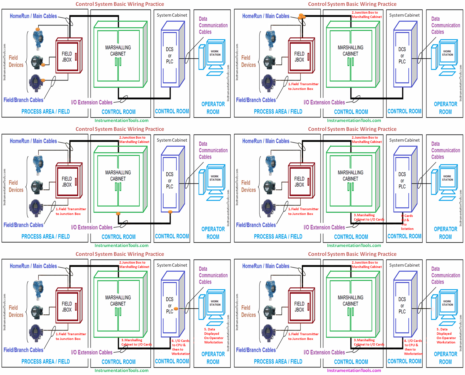
A PLC connection represents the signal flow starting from the field transmitters, junction box, marshalling cabinet, system cabinet and Human-Machine Interface for the operator graphic display.

Contents
PLC ConnectionPLC or DCS Signal Flow :Field Instruments to Junction boxWiring between Marshalling and System CabinetsSummary

PLC Connection

DCS and PLC Flow Diagram

Here we are discussing about traditional 4-20mA analog input devices only for ease of understanding the basic concept.

PLC or DCS Signal Flow :
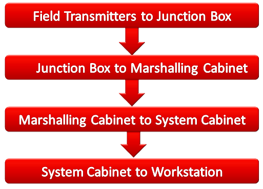
PLC or DCS Signal Flow

We have thousands of field transmitters installed in a process plant. So it is practically difficult to lay straight individual cables from each field transmitter to control room for displaying the process variables on the workstation.

As per design standards, particular number of field devices / transmitters are wired and terminated in a Field Junction box.

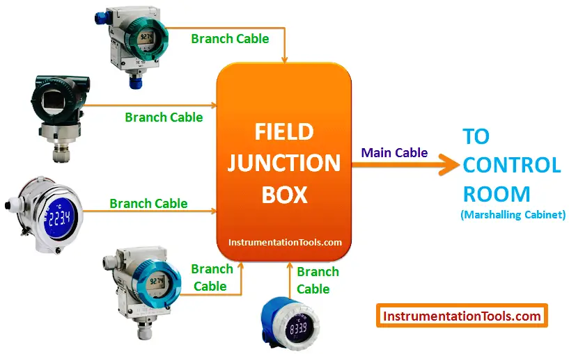
Cable used for connecting the field device to Junction box are called as Branch cables or field cables. Generally we use one pair cables for branch cables.

The below figure shows 5 field devices are connected to a Junction Box using individual Branch cables.

In this example, for carrying out these five signals to control room  we need minimum 5 pair cable (means one cable have 5 pairs) and also we have to consider spare cable requirement for future purpose.

so at least 6 pair cable or better a 12 pair cable best suits the below requirement.

Say we choose 12 pair cable and is nothing but a Main Cable or Home run cable as it interfaces the field junction box and marshalling cabinet in the control room.

so finally one big main cable is required and serves our purpose.

Field Instruments to Junction box
Field Instruments to Junction Box

In a Process plant, we have so many Junction boxes installed and connected with number of field devices.

Say we have 100 no’s of Junction boxes installed that means we have 100 no’s main cables are there which are coming from field to control room.

so practically it not possible to directly wire these main cables to analog input/output cards. To avoid these problems we use Marshalling cabinet for terminating these 100 no’s main cables.

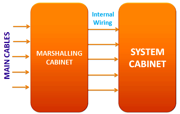
Marshalling cabinet main purpose is to provide main cables termination and then re-distribute the field devices to respective Analog Input/Output card using internal wiring.

Internal wiring will be used to connect from Marshalling cabinet to system cabinet.

Wiring between Marshalling and System Cabinets
Marshalling Cabinet to System Cabinet

System cabinet consists of Processor card (CPU), Analog Input Cards, Analog Output Cards, Communication cards etc.

Once Main cables are terminated in Marshalling cabinet, we have to take these field devices to the respective Analog input card channel.

so we use internal wiring to route these main cables/field devices from marshalling to system cabinet.

Once the main cables are connected to the Analog Input card via internal wiring and it converts the 4-20mA which is coming from field devices into equivalent Digital signal i.e. in Binary codes and the same will be communicated to Processor card.

The processor card performs as per the predefined or programmed instructions. The processor card may have inbuilt or separate Ethernet communication link which is used to display the measured process variables on the workstation.

Summary

The above animation depicts a typical cabling scheme that collects and distributes signals to and from the field devices.

A Field Junction Box is used to concentrate the signals into multi-conductor homerun cables or main cables.

The homerun cables then terminate in a remote or marshalling cabinet where the signals are marshalled (reorganized) as necessary to efficiently terminate at the I/O interface of the DCS or PLC system.

If you liked this article, then please subscribe to our YouTube Channel for PLC and SCADA video tutorials.

You can also follow us on Facebook and Twitter to receive daily updates.

Read Next:
  • What is Fieldbus?
  • PLC or DCS Systems
  • Top 100 PLC MCQ
  • PLC Valve Control Logic
  • What is SCADA?
Don't Miss Our Updates
Be the first to get exclusive content straight to your email.
We promise not to spam you. You can unsubscribe at any time.
Invalid email address
You've successfully subscribed !
Two Element Drum Level Control System
VFD Simulator Download – Free Yaskawa V1000 Software
PLC Program – Controls Conveyors ON and OFF Sequence
PLC Program for Water filling and Discharging Process
PLC Program for Counting Moving Objects on Conveyor
Share This Article
Facebook Whatsapp Whatsapp LinkedIn Copy Link
Share
19 Comments
  • Thorn says:
    August 18, 2016 at 9:24 am

    It helps me a lot..Im just a beginner and need something like this,,,,thanks for posting

    Reply
  • Jyoti says:
    December 11, 2016 at 7:42 pm

    Nice

    Reply
  • Ajit Kumar Prasad says:
    January 25, 2017 at 3:07 am

    Thanks brother

    Reply
  • Kamlesh sanchela says:
    March 10, 2017 at 9:02 am

    Thanks

    Reply
  • Gulam Ahmed Raza says:
    August 17, 2017 at 12:49 pm

    Nice knowledge site

    Reply
  • Kishor says:
    December 6, 2017 at 6:46 am

    Nice one

    Reply
  • ANKIT KUMAR DIVEWADI says:
    December 15, 2017 at 1:59 pm

    Best site ever seen. Nice collection

    Reply
  • abcde says:
    January 5, 2018 at 5:24 am

    How to do internal cross wiring for marshalling cabinet? please explain with animation or pics?

    Reply
  • Nikanth says:
    January 7, 2018 at 2:35 pm

    Thanks a lot. It really helps me a lot to understand the basics. The Best Website for Inst Guys.

    Reply
  • Ashik says:
    March 21, 2018 at 5:08 pm

    Ji super keep it up

    Reply
  • husasain says:
    June 5, 2018 at 2:07 pm

    is it true?
    that fieldbus can omit marshaling cabinet

    Reply
  • Faisal Hussain says:
    February 20, 2019 at 12:16 pm

    Wow thank allah it’s great web

    Reply
  • Faisal Hussain says:
    February 20, 2019 at 12:20 pm

    Thanks for helping

    Reply
  • Bipin Chaudhari says:
    September 3, 2019 at 12:07 pm

    thanks!

    Reply
  • ajay says:
    June 29, 2020 at 10:33 pm

    thanks a lot

    Reply
  • Essam says:
    August 25, 2020 at 7:23 pm

    Thank you very much

    Reply
  • MD IKBAL says:
    February 23, 2021 at 10:22 pm

    Verry use full knowledge
    Thanks Brother

    Reply
  • Suresh Mishra says:
    May 22, 2021 at 11:17 am

    Very good knowledge

    Reply
  • dilshad khan says:
    July 26, 2023 at 3:47 pm

    Great information for new one

    Reply

Leave a Reply Cancel reply

Your email address will not be published. Required fields are marked *

Stay Connected

128.3kFollowersLike
69.1kFollowersFollow
208kSubscribersSubscribe
38kFollowersFollow

Categories

Recent Comments

  • Guifty Shimica on Top Non-PLC Certification Courses for Automation Professionals
  • Guifty Shimica on Top Non-PLC Certification Courses for Automation Professionals
  • MIHARITSOA Aina Sitraka on Top Non-PLC Certification Courses for Automation Professionals
  • Vaishnavi on Free Instrumentation Course for Trainee Engineers

Related Articles

PLC based Drink Dispenser System

PLC based Drink Dispenser System

Pre-commissioning or Commissioning Activities

Pre-commissioning or Commissioning Activities

What is NEST loading in DCS

What is Nest Loading? – DCS and PLC Control Systems

PLC Program to control level of parallel tanks

Parallel Tanks Level Control using PLC Ladder Diagram Tutorial

Contextual HMI

What is Contextual HMI? – HMI Screens on a Mobile or Tablet

Ziegler-Nichols Closed Loop Tuning Procedure

Ziegler-Nichols Closed Loop Tuning Procedure

Ziegler-Nichols closed-loop Formula

Tuning a Temperature Process Control Loop

Instrumentation Logic Checks

How to Do Logic Checks During Plant Pre-Commissioning

More Articles

Demo of a SCADA Software – Level Control System

Thermocouple Voltage Curves

What are the Thermocouple Applications?

Digital Electronics Multiple Choice Questions

Hardware Description Language Objective Questions

Control Valve Working Animation

Control Valve Working Animation

Valve Pneumatic Actuator

What is a Pneumatic Actuator ?

Float Level Switch Principle

Float Level Switch Working Principle Animation

Electrical Cabinet Air Conditioner

Electrical Cabinet Air Conditioner – Enclosure Cooling, Maintenance

level control system

Practical Process Control System Questions & Answers – 11

Follow US
All rights reserved. Reproduction in whole or in part without written permission is prohibited.
Welcome Back!

Sign in to your account

Username or Email Address
Password

Lost your password?