Inst ToolsInst ToolsInst Tools
  • Courses
  • Automation
    • PLC
    • Control System
    • Safety System
    • Communication
    • Fire & Gas System
  • Instrumentation
    • Design
    • Pressure
    • Temperature
    • Flow
    • Level
    • Vibration
    • Analyzer
    • Control Valve
    • Switch
    • Calibration
    • Erection & Commissioning
  • Interview
    • Instrumentation
    • Electrical
    • Electronics
    • Practical
  • Q&A
    • Instrumentation
    • Control System
    • Electrical
    • Electronics
    • Analog Electronics
    • Digital Electronics
    • Power Electronics
    • Microprocessor
  • Request
Search
  • Books
  • Software
  • Projects
  • Process
  • Tools
  • Basics
  • Formula
  • Power Plant
  • Root Cause Analysis
  • Electrical Basics
  • Animation
  • Standards
  • 4-20 mA Course
  • Siemens PLC Course
Reading: DC Motor Connections
Share
Font ResizerAa
Inst ToolsInst Tools
Font ResizerAa
  • Courses
  • Design
  • PLC
  • Interview
  • Control System
Search
  • Courses
  • Automation
    • PLC
    • Control System
    • Safety System
    • Communication
    • Fire & Gas System
  • Instrumentation
    • Design
    • Pressure
    • Temperature
    • Flow
    • Level
    • Vibration
    • Analyzer
    • Control Valve
    • Switch
    • Calibration
    • Erection & Commissioning
  • Interview
    • Instrumentation
    • Electrical
    • Electronics
    • Practical
  • Q&A
    • Instrumentation
    • Control System
    • Electrical
    • Electronics
    • Analog Electronics
    • Digital Electronics
    • Power Electronics
    • Microprocessor
  • Request
Follow US
All rights reserved. Reproduction in whole or in part without written permission is prohibited.
Inst Tools > Blog > Electrical Theory > DC Motor Connections

DC Motor Connections

Last updated: July 29, 2018 12:07 pm
Editorial Staff
Electrical Theory
No Comments
Share
2 Min Read
SHARE

There are various types of DC motors found in industry today. Each type contains various characteristics that makes it desirable for certain applications.

DC Motor Connections

The below Figure shows schematic- ally the different methods of connecting the field and armature circuits in a DC motor. The circular symbol represents the armature circuit, and the squares at the side of the circle represent the brush commutator system. The direction of the arrows indicates the direction of the magnetic fields.

DC Motor Connections

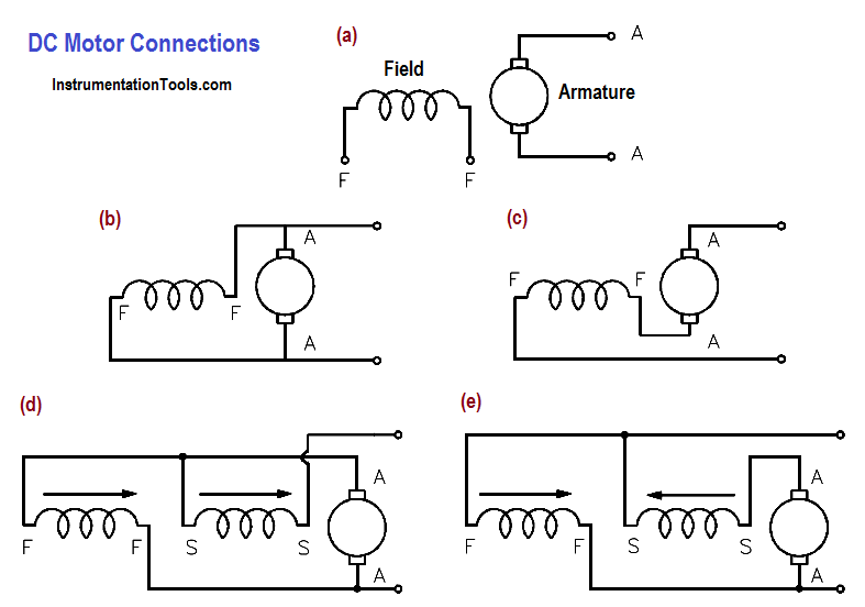
Figure 7 : DC Motor Connections

Figure 7a shows an externally-excited DC motor. This type of DC motor is constructed such that the field is not connected to the armature. This type of DC motor is not normally used.

Figure 7b shows a shunt DC motor. The motor is called a “shunt” motor because the field is in parallel, or “shunts” the armature.

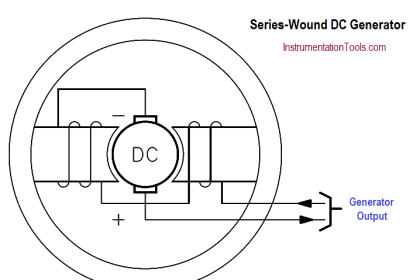
Figure 7c shows a series DC motor. The motor field windings for a series motor are in series with the armature.

Figures 7d and 7e show a compounded DC motor. A compounded DC motor is constructed so that it contains both a shunt and a series field.

Figure 7d is called a “cumulatively-compounded” DC motor because the shunt and series fields are aiding one another.

Figure 7e is called a “differentially-compounded” DC motor because the shunt and series field oppose one another.

Don't Miss Our Updates
Be the first to get exclusive content straight to your email.
We promise not to spam you. You can unsubscribe at any time.
Invalid email address
You've successfully subscribed !

Continue Reading

Power Factor
DC Motor Torque
Series Resistance
Battery Hazards
Rectifiers, Forward Bias and Reverse Bias
Battery Operation : Series and Parallel
Share This Article
Facebook Whatsapp Whatsapp LinkedIn Copy Link
Share
Leave a Comment

Leave a Reply Cancel reply

Your email address will not be published. Required fields are marked *

Stay Connected

128.3kFollowersLike
69.1kFollowersFollow
210kSubscribersSubscribe
38kFollowersFollow

Categories

Explore More

Series Short Circuit Faults
Capacitance and Capacitive Reactance
Compound Generators
AC Motor Theory
AC Induction Motor Slip
Batteries Theory
Ohm Meter
Electrical Wiring Terminology

Keep Learning

AC Generator Operation

Types of AC Generators

Transformer Efficiency

Transformer Efficiency

AC Generator Operation

Losses in AC Generator

Transformer Efficiency and Loses Formula

Transformer Losses and Efficiency

Split Phase Motor

Single Phase AC Induction Motors

Phase angle

AC Generation Analysis : Effective Values, Phase Angle and Frequency

Potential Difference Across a Conductor Causes a Current to Flow

Conductor, Insulator, Resistor and Current Flow

Series - Wound DC Motor

Series-Wound Motor

Learn More

electrical-drives-questions-answers

Electrical Drives Questions & Answers

Needle Valve Schematic

How Needle Valve Works ?

Ziegler-Nichols Closed Loop Tuning Procedure

Ziegler-Nichols Closed Loop Tuning Procedure

Fiber Optic Patch Cord

What is a Fiber Optic Patch Cord? – Types, Explained

3-way solenoid valve Normally Open

What is a 3-way Solenoid Valve ?

Temperature Measurement Questions

Interview Questions on Temperature Measurement

MCQ on Measurement and Instrumentation

MCQ on Measurement and Instrumentation

Series Circuit

Series Circuit

Menu

  • About
  • Privacy Policy
  • Copyright

Quick Links

  • Learn PLC
  • Helping Hand
  • Part Time Job

YouTube Subscribe

Follow US
All rights reserved. Reproduction in whole or in part without written permission is prohibited.
Welcome Back!

Sign in to your account

Username or Email Address
Password

Lost your password?