The tubes within a Coriolis flowmeter are shaken at their mechanical resonant frequency to maximize their shaking motion while minimizing electrical power applied to the force coil.
Multi-Variable Transmitter
The electronics module uses a feedback loop between the sensor coils and the shaker coil to maintain the tubes in a continuous state of resonant oscillation.
This resonant frequency changes with process fluid density, since the effective mass of the fluid-filled tubes changes with process fluid density (Note 1) , and mass is one of the variables influencing the mechanical resonant frequency of any elastic structure.
Note 1: If you consider each tube as a container with a fixed volume capacity, a change in fluid density (e.g. pounds per cubic foot) must result in a change in mass for each tube.
Note the “mass” term in the following formula, describing the resonant frequency of a tensed string:
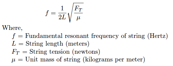
A fluid-filled tube is a close analogue to a tensed string, with tube stiffness analogous to string tension and liquid density analogous to unit mass. So long as the spring constant (tube stiffness) is known, the resonant frequency of the tubes’ vibration serves to indicate the unit mass of the tubes, which in turn represents fluid density given the known internal volume of the tubes.
Temperature changes have the potential to interfere with this density measurement, because temperature affects the elasticity of metal (Young’s modulus) as well as the tubes’ physical dimensions.
This is why all Coriolis flowmeters are equipped with RTD temperature sensors to continuously monitor the temperature of the vibrating tubes. The flowmeter’s microprocessor takes this tube temperature measurement and uses it to compensate for the resulting elasticity and dimensional changes based on a prior modeling of the tube metal characteristics.
In other words, the flowmeter’s microprocessor continuously updates the force variable (FT ) representing tube stiffness in the resonant frequency equation so that the frequency will always be a reliable indicator of unit mass (fluid density).
This temperature measurement happens to be accessible as an auxiliary output signal, which means a Coriolis flowmeter may double as a (very expensive!) temperature (Note 2) transmitter in addition to measuring mass flow rate and fluid density.
Note 2: An important caveat is that the RTD sensing tube temperature in a Coriolis flowmeter really senses the tubes’ outside skin temperature, which may not be exactly the same as the temperature of the fluid inside the tube. If the ambient temperature near the flowmeter differs substantially from the fluid’s temperature, the tube skin temperature reading may not be accurate enough for the flowmeter to double as a fluid temperature transmitter.
The ability to simultaneously measure three process variables (mass flow rate, temperature, and density) makes the Coriolis flowmeter a very versatile instrument indeed. This is especially true when the flowmeter in question communicates digitally using a “fieldbus” standard rather than an analog 4-20 mA signal.
Fieldbus communication allows multiple variables to be transmitted by the device to the host system (and/or to other devices on the same fieldbus network), allowing the Coriolis flowmeter to do the job of three instruments!
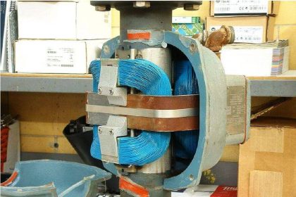
Coriolis Mass Flow Meter
An example of a Coriolis mass flowmeter being used as a multi-variable transmitter appears in the following photographs.
Note the instrument tag labels in the close-up photograph (FT, TT, and DT), documenting its use as a flow transmitter, temperature transmitter, and density transmitter, respectively:


If you liked this article, then please subscribe to our YouTube Channel for Instrumentation, Electrical, PLC, and SCADA video tutorials.
You can also follow us on Facebook and Twitter to receive daily updates.
Read Next:
- Pressure based Flowmeters
- Mass Flow Calculations
- Inferential Measurement
- Mass Spectrometer Principle
- Magnetic Flow Meter Animation