Inst ToolsInst ToolsInst Tools
  • Courses
  • Automation
    • PLC
    • Control System
    • Safety System
    • Communication
    • Fire & Gas System
  • Instrumentation
    • Design
    • Pressure
    • Temperature
    • Flow
    • Level
    • Vibration
    • Analyzer
    • Control Valve
    • Switch
    • Calibration
    • Erection & Commissioning
  • Interview
    • Instrumentation
    • Electrical
    • Electronics
    • Practical
  • Q&A
    • Instrumentation
    • Control System
    • Electrical
    • Electronics
    • Analog Electronics
    • Digital Electronics
    • Power Electronics
    • Microprocessor
  • Request
Search
  • Books
  • Software
  • Projects
  • Process
  • Tools
  • Basics
  • Formula
  • Power Plant
  • Root Cause Analysis
  • Electrical Basics
  • Animation
  • Standards
  • 4-20 mA Course
  • Siemens PLC Course
Reading: Control Valve Fail Safe Action
Share
Font ResizerAa
Inst ToolsInst Tools
Font ResizerAa
  • Courses
  • Design
  • PLC
  • Interview
  • Control System
Search
  • Courses
  • Automation
    • PLC
    • Control System
    • Safety System
    • Communication
    • Fire & Gas System
  • Instrumentation
    • Design
    • Pressure
    • Temperature
    • Flow
    • Level
    • Vibration
    • Analyzer
    • Control Valve
    • Switch
    • Calibration
    • Erection & Commissioning
  • Interview
    • Instrumentation
    • Electrical
    • Electronics
    • Practical
  • Q&A
    • Instrumentation
    • Control System
    • Electrical
    • Electronics
    • Analog Electronics
    • Digital Electronics
    • Power Electronics
    • Microprocessor
  • Request
Follow US
All rights reserved. Reproduction in whole or in part without written permission is prohibited.
Inst Tools > Blog > Control Valves > Control Valve Fail Safe Action

Control Valve Fail Safe Action

Last updated: July 25, 2019 12:00 pm
Editorial Staff
Control Valves
3 Comments
Share
5 Min Read
SHARE

There are two primary system considerations centering around an emergency operational situation for control valves.

Contents
Control Valve Fail Safe ActionI. Loss of Instrument Air Supply Pressurea.) Fully Closeb. Fully Openc.) In Last Positiond.) Continue ThrottlingII. Loss of Electrical Powera.) Fully Closeb.) Fully Openc.) In Last Position

Control Valve Fail Safe Action

I. Loss of instrument air supply (IAS) pressure

II. Loss of electrical power

There are four choices as to control valve “response” to the emergency condition :

a.) Fully Close

b.) Fully Open

c.) In Last Position

d.) Continue Throttling

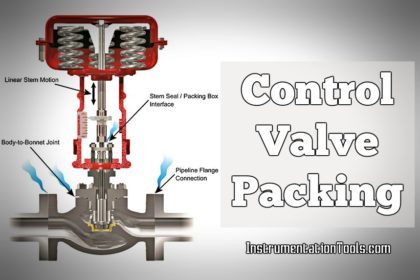
For either fail-safe loss of IAS or loss of electrical power, it is the actuator’s benchset range spring that “drives” the control valve’s plug to its fail-safe open or closed position.

I. Loss of Instrument Air Supply Pressure

a.) Fully Close

The actuator’s benchset range spring “drives” the valve plug “closed” when loading air pressure goes towards or near 0 psig. (ATO-FC “Reverse”)

Loss of Instrument Air Supply to Control Valve

Because IAS piping systems can be extensive (big), the IAS can decay too slowly causing operational problems.

In such cases it may be desirable to use a 3-way pilot switching valve to “anticipate” the eventual loss of IAS and quickly stroke the control valve to its fail-safe position, eliminating the transitory operational effects of the slow decay.

b. Fully Open

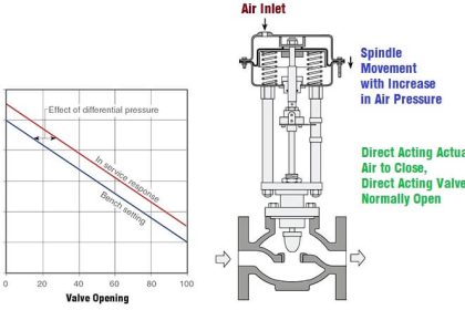
The actuator’s benchset range spring “drives” the valve plug “open” when loading air pressure goes toward or near 0 psig. (ATC-FO “Direct”)

A similar scheme to I.a. previous may be applied for ATCFO arrangements for fail open control valves to eliminate transitory effects.

c.) In Last Position

This is accomplished with a “lockup valve”, which is a 2- way pilot switching valve. If the air pressure is lost from the control loop’s airset, the lockup valve will “close” and “trap” the air within the actuator’s loading chamber.

If no air leaks are present, the control valve will stay at the last throttling position. Such loops are normally “local”. (Control valve action is a non-issue.)

Control Valve in Last Position

d.) Continue Throttling

This is an “elaborate” system that can be accomplished two different ways

i.) Volume Tank

A volume tank stores a limited supply of IAS to sustain normal operation for a finite time period, i.e. approximately up to a hour.

Volume Booster for Control Valve

ii.) Alternate Supply

A high pressure cylinder is on standby with an alternate gas, usually GN2. If IAS pressure falls below 50 psig, the alternate gas will take over to supply pneumatic control. The high pressure will allow for several hours of sustained operation, enough time for the emergency loss of the IAS to be restored.

Such applications are normally for “very important (critical)” services. Such loops are normally “local” and pneumatic only; i.e. no electrical power involved except the low pressure alarm switch.

Control Valve Alternate Air Supply

II. Loss of Electrical Power

Protection for loss of electrical power is indirectly accomplished thru the use of a solenoid valve. In normal operation the solenoid valve is energized electrically; in an emergency loss of electrical power the solenoid valve is de-energized and trips to the “shelf-position”. Solenoid voltage can be 120 VAC, 240 VAC, 125 VDC, 24 VDC, etc.

a.) Fully Close

By blocking the LOAD air to the actuator and venting the air within the actuator’s loading chamber to atmosphere (P = 0 psig), the actuator’s benchset range spring “drives” the valve plug “closed”. The solenoid valve is a 3-way type.

Control Valve Loss of Power

b.) Fully Open

By blocking the air to the actuator and venting the air within the actuator’s loading chamber to atmosphere (P= 0 psig), the actuator’s benchset range spring “drives” the valve plug open. The solenoid valve and tubing interconnection is identical to the II.a. case previous.

c.) In Last Position

This is accomplished with a 2-way solenoid valve. In the “energized” condition, the solenoid valve ports are “open”; loading air passes thru. In the “de-energized” condition, the solenoid valve “closes” and traps the air within the actuator’s loading chamber.

If no air leaks are present, the control valve will stay at the last throttling position. (Control valve action is a non-issue.)

Control Valve Fail Safe

Abbreviations :

  • IAS : Instrument Air Supply
  • FTC : Fail to Close
  • FTO : Fail to Open
  • FO : Fail Open
  • FC : Fail Close
  • S/SV : Solenoid Valve

Articles You May Like :

Solenoid Valves Questions

What is 3-way Solenoid Valve ?

PLC Valve Control Ladder Logic

How Diaphragm Valves Work ?

Solenoid Valve’s Energized

Don't Miss Our Updates
Be the first to get exclusive content straight to your email.
We promise not to spam you. You can unsubscribe at any time.
Invalid email address
You've successfully subscribed !

Continue Reading

Air Filter Regulator Working Principle Animation
What is Split Range Control Loop ?
How Ball Valves Work ?
What is an Altitude Valve?
Pressure Relief Valve Principle
Difference between Butterfly Valves and Ball Valves
Share This Article
Facebook Whatsapp Whatsapp LinkedIn Copy Link
Share
3 Comments
  • Priyadarshini says:
    October 11, 2016 at 8:16 am

    hi sir,

    Thank you very much for doing this incredible work!!! this website is highly informative and very useful to instrumentation engineers like me!!!keep doing this great job!!!!

    Many thanks once again!!!

    Reply
  • Priyadarshini says:
    October 11, 2016 at 8:27 am

    Hi Sir,

    i have a question if i have a control valve, which is actuated by an interlock via a solenoid under trip conditions and if the fail position of the control valve is FLC.
    Can you please explain what will be the position of the valve and how it is established during
    1. Loss of instrument air supply
    2.Loss of electric power

    Reply
    • S Bharadwaj Reddy says:
      October 11, 2016 at 11:46 am

      In case of loss of air supply or power, the valve will be in Close Position.

      Reply

Leave a Reply Cancel reply

Your email address will not be published. Required fields are marked *

Stay Connected

128.3kFollowersLike
69.1kFollowersFollow
210kSubscribersSubscribe
38kFollowersFollow

Categories

Explore More

Common Valve Abbreviations in US Engineering Drawings
What is a Electric Motor Actuator ?
Short Notes on Different Valve Types
Solenoid Valve Troubleshooting Tips
What is ON/OFF Valve ?
What is a Disc Valve ?
What is Needle Valve ?
What is Motor Actuator ?

Keep Learning

Piping Schematic for Two Solenoid Valves Double Acting

Different Types of Control Valve Actuators

Types of Failures in Control Valves

Types of Failures in Control Valves

Installation of a Control Valve

How to Install a Control Valve?

What is a Servo Valve?

What is a Servo Valve? – Principle and Advantages

Rupture Disc

Working of Rupture Disk

control valve sizing problem

Importance of Proper Control Valve Sizing

Types of Control Valves Noise

Types of Control Valves Noise

valve plug and seat damage

Control Valve Erosion Problems

Learn More

HAZOP

What is HAZOP ?

Basics of FOUNDATION Fieldbus

Difference between Fieldbus, Profibus and HART Protocols

Steady-state process gain

Steady-State Process Gain

Power Plant Blackout

What Happens When the Power Plant Blackout?

Electrical Machines Questions and Answers

Salient Pole Machines Quiz

PLC Power Supply and Operating Voltages

PLC Power Supply and Operating Voltages

Omron PLC for Product Painting with Integrated Weighing System

Omron PLC for Product Painting with Integrated Weighing System

Pressure Gauge with Syphons

Pressure Gauge Syphons Principle

Menu

  • About
  • Privacy Policy
  • Copyright

Quick Links

  • Learn PLC
  • Helping Hand
  • Part Time Job

YouTube Subscribe

Follow US
All rights reserved. Reproduction in whole or in part without written permission is prohibited.
Welcome Back!

Sign in to your account

Username or Email Address
Password

Lost your password?