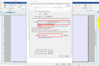
Learn how to control lamps using the Schneider PLC EcoStruxure Machine Expert software with Sequential Timer program. With a Timer, we can make a device or system Run according to a predetermined schedule and sequence. In this example of a Sequential Timer System program, there will be 3 Lamps that will be turned ON sequentially at different time intervals, then they can be turned OFF sequentially at different intervals.
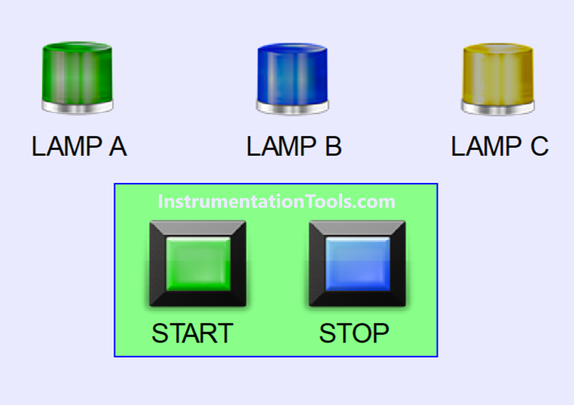
Control Lamps Sequences
The following are the inputs of PLC.
- The PB_START (I0.0) button is used to turn ON the system.
- The PB_STOP (I0.1) button is used to turn OFF the system.
This PLC program has 2 sequences:
SEQUENCE-1
This sequence will Start running if the PB_START (I0.0) button is Pressed and when Sequence-1 is running, the value in memory word SEQUENCE (MW0) will become “1”.
When the PB_START (I0.0) button has been Pressed, the LAMP_A (Q0.0) Lamp will turn ON for the first time and the LAMP_B (Q0.1) Lamp will turn ON 5 seconds later.
The Lamp LAMP_C (Q0.2) will turn ON 3 seconds later.
SEQUENCE 2
Sequence-2 can only be executed when the LAMP_C (Q0.2) Lamp is ON.
This sequence will Start running if the PB_STOP (I0.1) button is Pressed and when Sequence-2 Runs, the value in memory word SEQUENCE (MW0) will become “2”.
When the PB_STOP (I0.1) button is Pressed, the Lamp LAMP_C (Q0.2) will turn Off first and followed by Lamp LAMP_B (Q0.1) 4 seconds later.
5 seconds later, the LAMP_A (Q0.0) Lamp will turn OFF.
The memory word SEQUENCE (MW0) will be set to zero “0” when the LAMP_A (Q0.0), LAMP_B (Q0.1), and LAMP_C (Q0.2) Lamp are all OFF or ON.
Addressing of PLC Program
| Comment | Input (I) | Output (Q) | Memory Word | Memory Bits | Timer |
| PB_START | I0.0 | ||||
| PB_STOP | I0.1 | ||||
| LAMP_A | Q0.0 | ||||
| LAMP_B | Q0.1 | ||||
| LAMP_C | Q0.2 | ||||
| TIMERA1 | TM0 | ||||
| TIMERA2 | TM1 | ||||
| TIMERB1 | TM2 | ||||
| TIMERB2 | TM3 | ||||
| SEQUENCE_1 | M0 | ||||
| SEQUENCE_2 | M1 | ||||
| TIMER_1A | M2 | ||||
| TIMER_2A | M3 | ||||
| TIMER_1B | M4 | ||||
| TIMER_2B | M5 | ||||
| SEQUENCE | MW0 |
Schneider PLC Logic
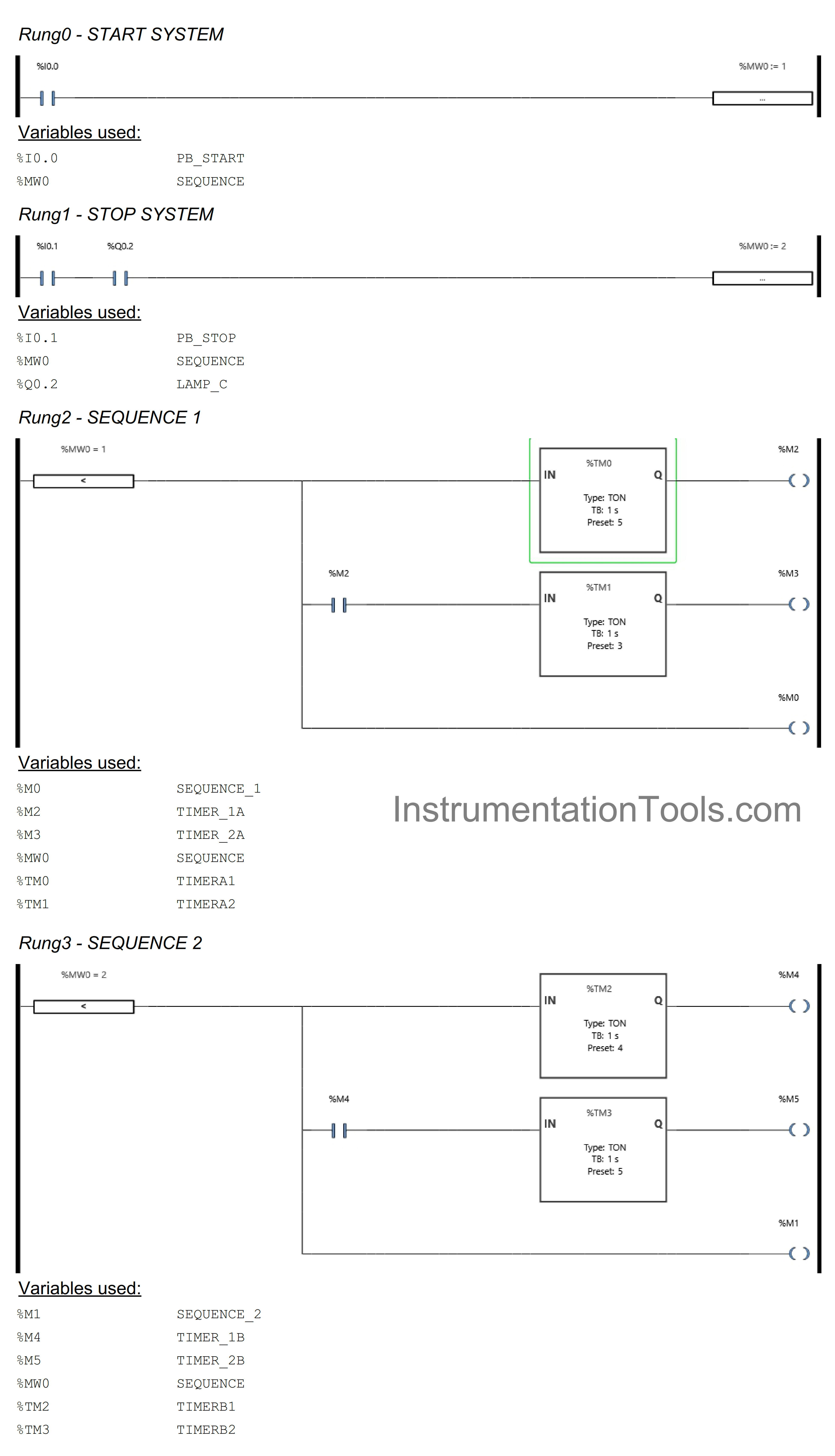
RUNG 0 (START SYSTEM)
In this Rung, the value in the memory word SEQUENCE (MW0) becomes “1” if the PB_START (I0.0) button is pressed, so the system will Run in Sequence-1 mode.
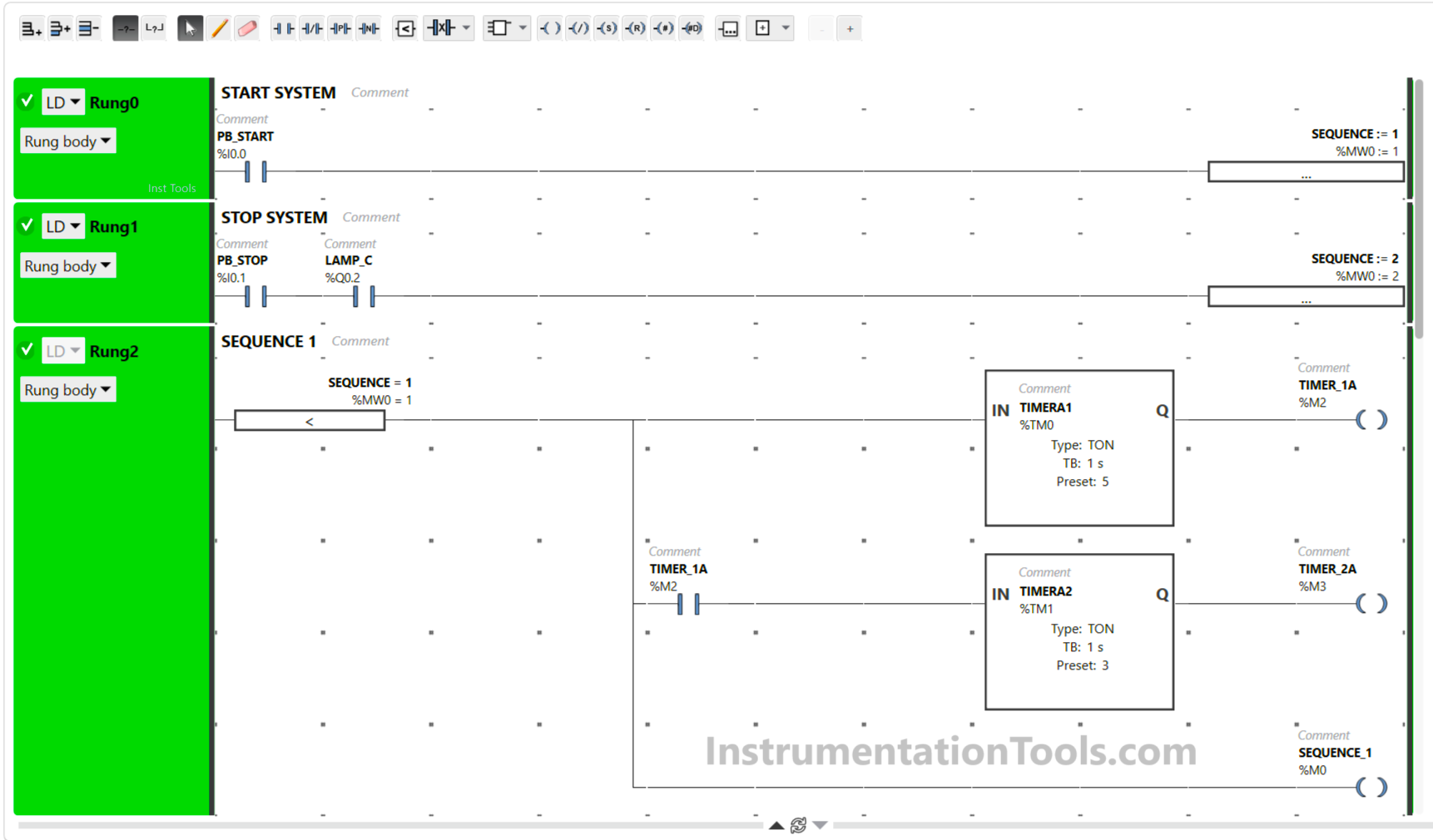
RUNG 1 (STOP SYSTEM)
In this Rung, the value in memory word SEQUENCE (MW0) becomes “2” when the PB_STOP (I0.1) button is Pressed and the NO contact of Output LAMP_C (Q0.2) is ON so that the system Runs in Sequence-2 mode.
RUNG 2 (SEQUENCE 1)
The memory bit SEQUENCE_1 (M0) will be in the HIGH state when the value in memory word SEQUENCE (MW0) is Equal to “1”. The timer TIMERA1 (TM0) Starts counting up to 5 seconds and after finished counting the memory bit TIMER_1A (M2) will be in the HIGH state.
When the NO contact of memory bit TIMER_1A (M2) in the HIGH state, the Timer TIMERA2 (TM1) will count for up to 3 seconds and when it has finished counting the memory bit TIMER_2A (M3) will be in the HIGH state.
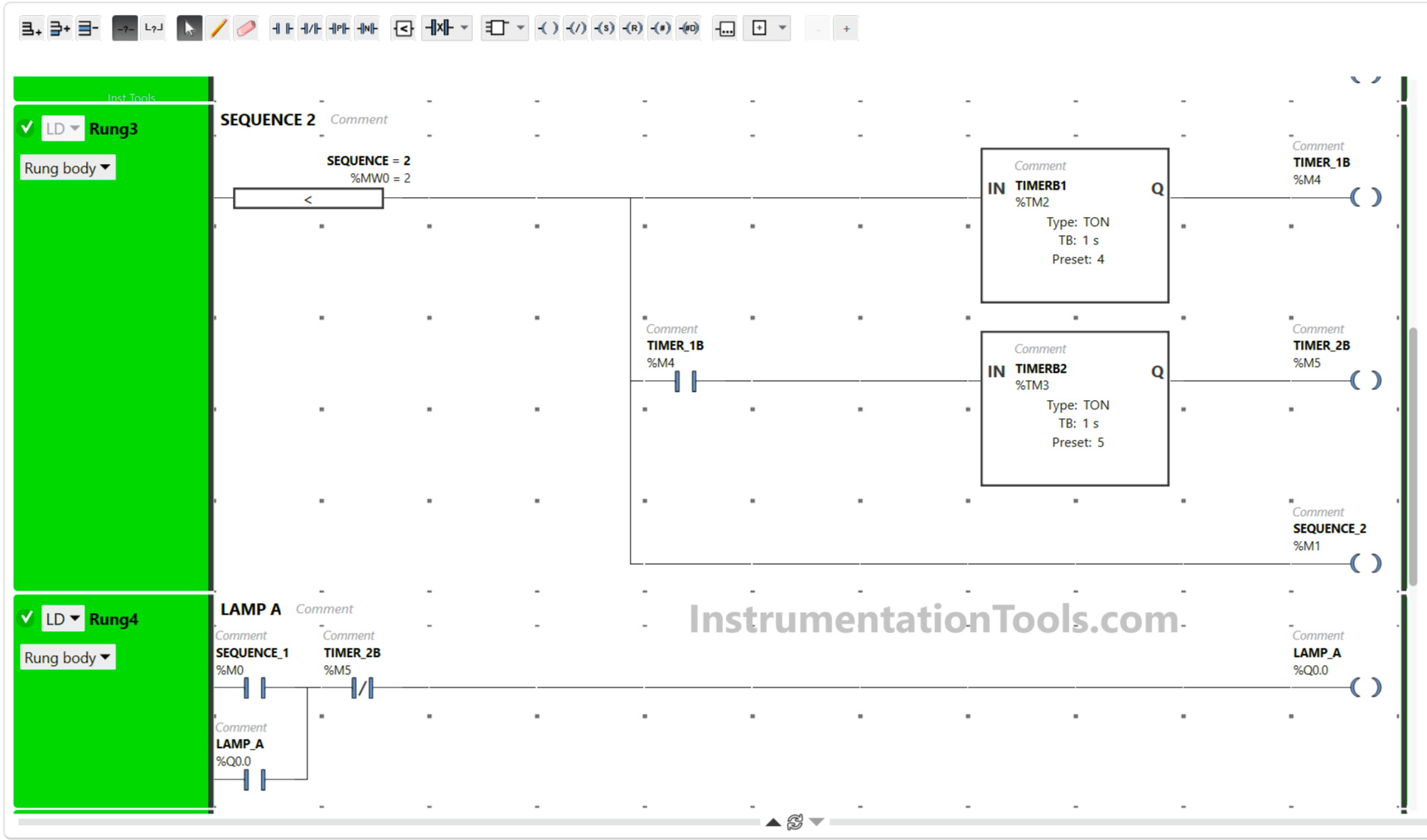
RUNG 3 (SEQUENCE 2)
The memory bit SEQUENCE_1 (M0) will be in the HIGH state if the value in memory word SEQUENCE(MW0) is Equal to “2”. The timer TIMERB1 (TM2) Starts counting up to 4 seconds and after finished counting the memory bit TIMER_1B (M4) will be in the HIGH state.
When the NO contact of memory bit TIMER_1B (M4) in the HIGH state, the Timer TIMERB2 (TM3) will count for up to 5 seconds and when it has finished counting the memory bit TIMER_2B (M5) will be in the HIGH state.
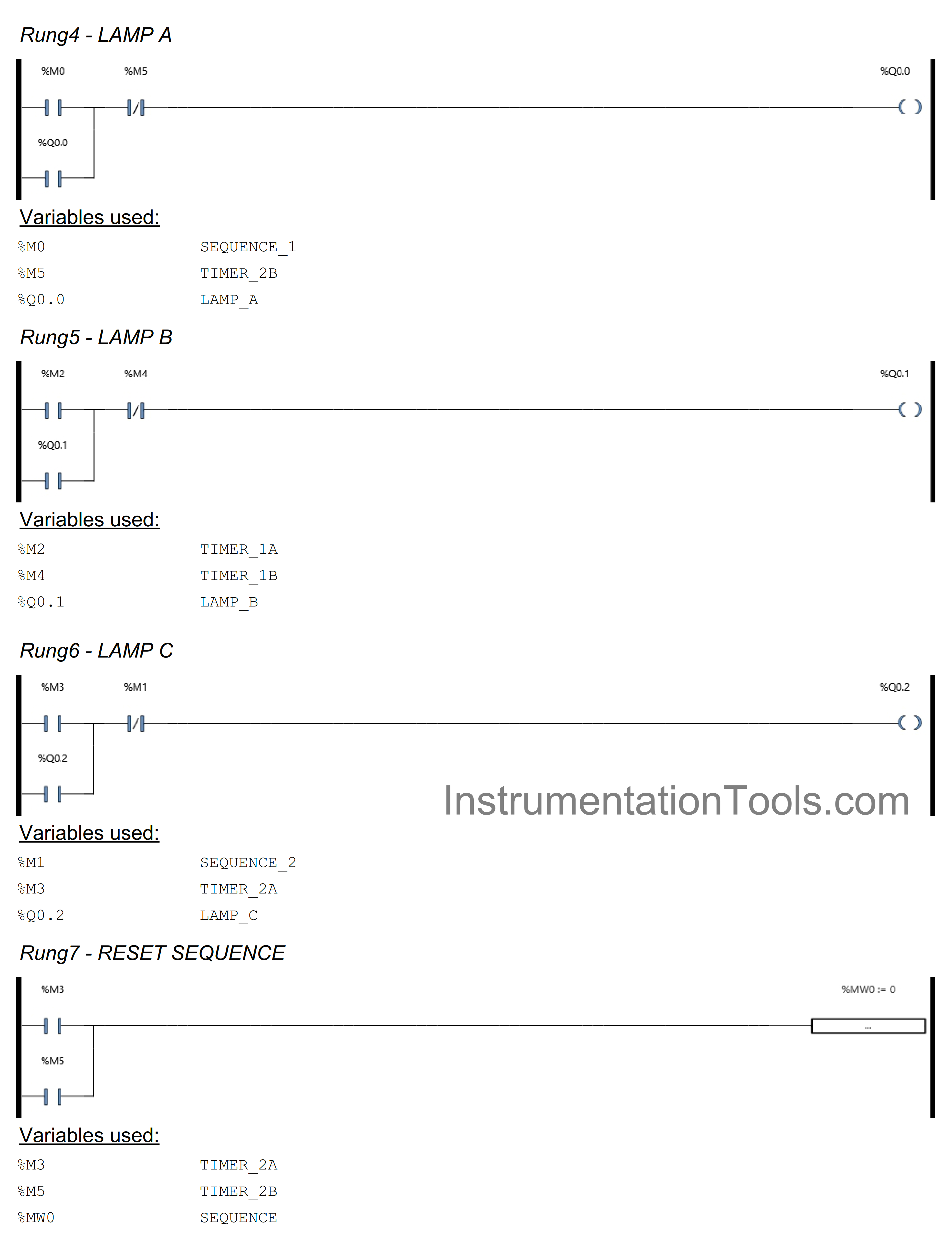
RUNG 4 (LAMP A)
In this Rung, Output LAMP_A(Q0.0) will be ON if the NO contact of memory bit SEQUENCE_1 (M0) is in the HIGH state. The LAMP_A (Q0.0) output will remain in the ON state even though the NO contact of memory bit SEQUENCE_1 (M0) is in the LOW state, because it uses Latching.
When the NC contact of memory bit TIMER_2B (M5) is in the HIGH state, the LAMP_A (Q0.0) output will be OFF.
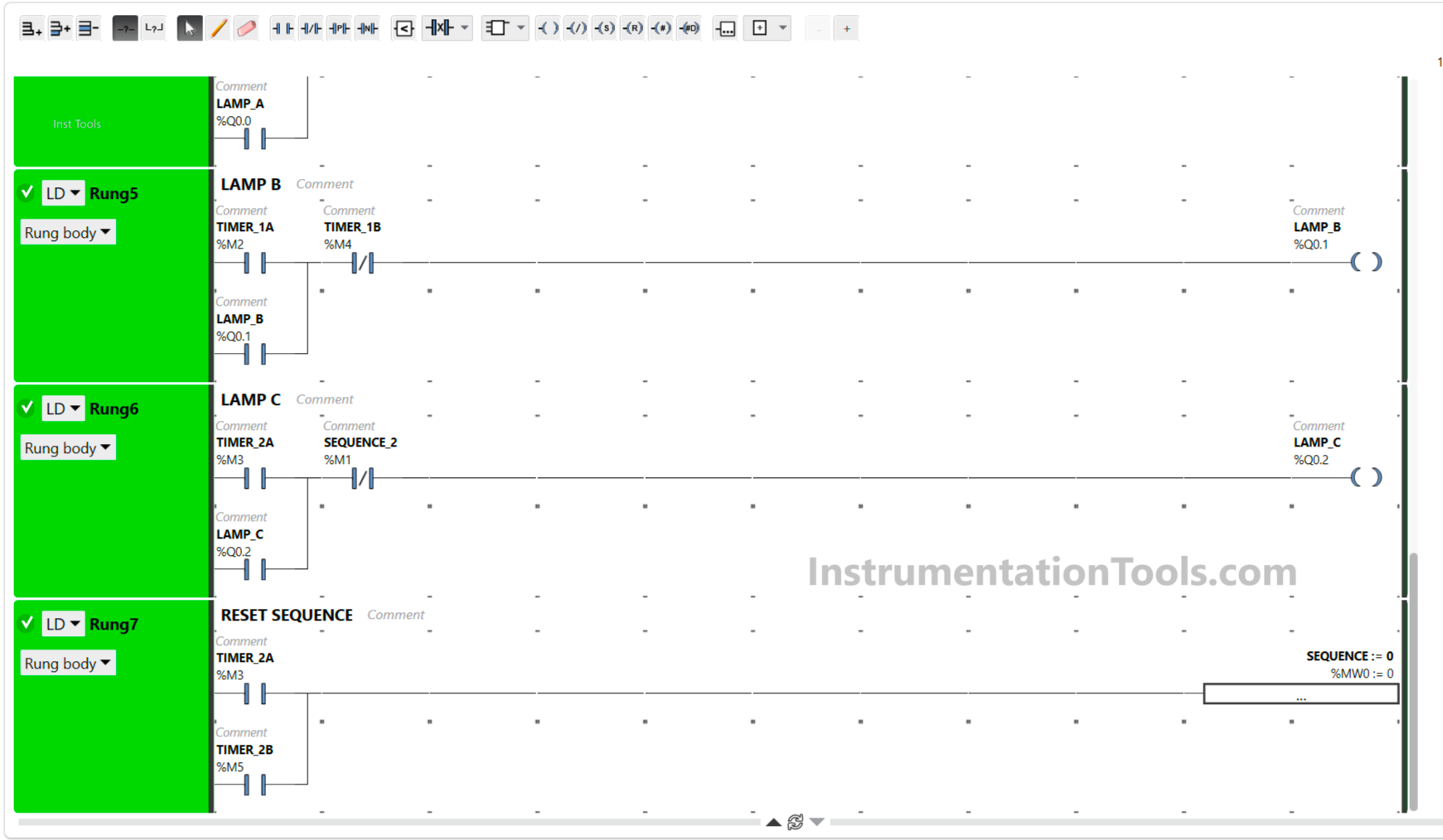
RUNG 5 (LAMP B)
In this Rung, Output LAMP_B (Q0.1) will be ON when the NO contact of memory bit TIMER_1A (M3) is in the HIGH state. The LAMP_B (Q0.1) output will remain in the ON state even though the NO contact of memory bit TIMER_1A (M3) in the LOW state because it uses Latching.
If the NC contact of memory bit TIMER_1B (M4) is in the HIGH state, then the LAMP_B (Q0.1) Output will be OFF.
RUNG 6 (LAMP C)
In this Rung, the LAMP_C (Q0.2) output will be ON when the NO contact of memory bit TIMER_2A (M3) in the HIGH state. The LAMP_C (Q0.2) output will remain in the ON state even though the NO contact of memory bit TIMER_2A (M3) in the LOW state because it uses Latching.
If the NC contact of memory bit SEQUENCE_2 (M1) is in the HIGH state, Output LAMP_C (Q0.2) will be OFF.
RUNG 7 (RESET SEQUENCE)
In this Rung, the memory word SEQUENCE (MW0) will become zero value “0” when the NO contact of memory bit TIMER_2A (M3) or memory bit TIMER_2B (M5) in the HIGH state.
Because the Operation block will move the zero value “0” to the memory word SEQUENCE (MW0).
Read Next:
- Simple Conveyor Control PLC Program Example
- PLC Sequential Control of Three Lights with Reset
- PLC Batch System for 4 Tanks Mixing Program
- Basic PLC Conveyor System for Product Handling
- PLC Programming for Weight-Based Packaging