Inst ToolsInst ToolsInst Tools
  • Courses
  • Automation
    • PLC
    • Control System
    • Safety System
    • Communication
    • Fire & Gas System
  • Instrumentation
    • Design
    • Pressure
    • Temperature
    • Flow
    • Level
    • Vibration
    • Analyzer
    • Control Valve
    • Switch
    • Calibration
    • Erection & Commissioning
  • Interview
    • Instrumentation
    • Electrical
    • Electronics
    • Practical
  • Q&A
    • Instrumentation
    • Control System
    • Electrical
    • Electronics
    • Analog Electronics
    • Digital Electronics
    • Power Electronics
    • Microprocessor
  • Request
Search
  • Books
  • Software
  • Projects
  • Process
  • Tools
  • Basics
  • Formula
  • Power Plant
  • Root Cause Analysis
  • Electrical Basics
  • Animation
  • Standards
  • 4-20 mA Course
  • Siemens PLC Course
Reading: How to Commission WirelessHART Transmitter With Gateway
Share
Font ResizerAa
Inst ToolsInst Tools
Font ResizerAa
  • Courses
  • Design
  • PLC
  • Interview
  • Control System
Search
  • Courses
  • Automation
    • PLC
    • Control System
    • Safety System
    • Communication
    • Fire & Gas System
  • Instrumentation
    • Design
    • Pressure
    • Temperature
    • Flow
    • Level
    • Vibration
    • Analyzer
    • Control Valve
    • Switch
    • Calibration
    • Erection & Commissioning
  • Interview
    • Instrumentation
    • Electrical
    • Electronics
    • Practical
  • Q&A
    • Instrumentation
    • Control System
    • Electrical
    • Electronics
    • Analog Electronics
    • Digital Electronics
    • Power Electronics
    • Microprocessor
  • Request
Follow US
All rights reserved. Reproduction in whole or in part without written permission is prohibited.
Inst Tools > Blog > Calibration > How to Commission WirelessHART Transmitter With Gateway

How to Commission WirelessHART Transmitter With Gateway

Last updated: June 21, 2019 3:12 pm
Editorial Staff
Calibration
No Comments
Share
4 Min Read
SHARE

WirelessHART Transmitter With Gateway

This guide is intended to give an idea on how to use 375/475 Field Communicator to configure Rosemount wireless device to be connected to wireless gateway

  • A Field Communicator is used to configure HART devices.   WirelessHART devices are preconfigured using the same tools and methods used on wired HART devices. However, WirelessHART devices require the additional configuration of the Join Key and Network ID to join the correct wireless network.
  • A device uses the Network ID to determine which wireless network to join in a large installation spanning multiple process areas.  Once the device has heard one or more neighbors, it uses the Join Key to encrypt the join messages exchanged with the network manager.
  • The network manager, in turn, authenticates the device and incorporates the device into the network.
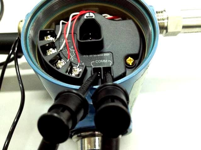
  • The  Field Communicator connects to wireless devices through the devices’ FSK (frequency-shift keying) communication terminals.
  • The Field Communicator connects directly to the communication terminals on a wireless device.
  • Once connected, the field communicator automatically polls for connected devices using the selected polling options.

Follow below steps : 

STEP 1 : Plug the Connector set into HART terminal at 375/475

Plug the Connector set into HART terminal

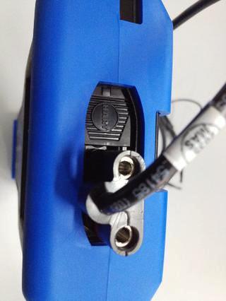
STEP 2 : Clip the other end of Connector to the COMM terminal.

Wireless HART Transmitter

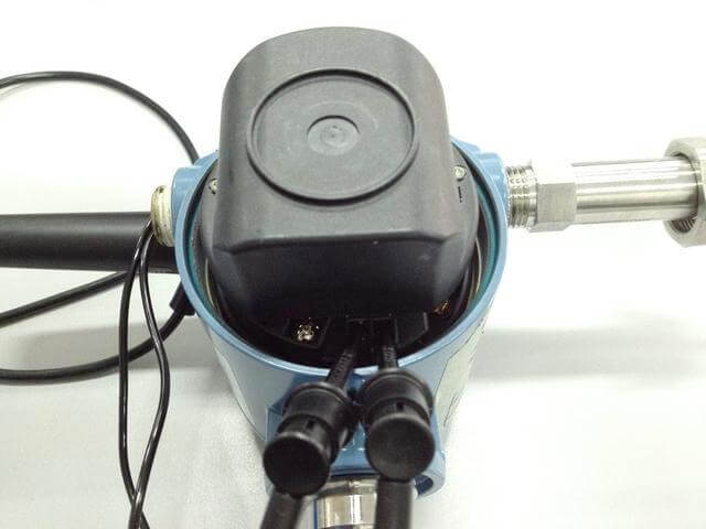
STEP 3 : Insert the Battery module into the dedicated slot

Wireless HART Transmitter Battery

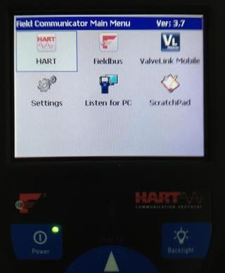
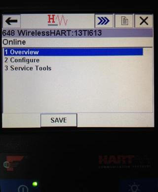
STEP 4 : Power Up the 375/475. Select the “HART” icon and press “Enter” keypad to communicate with the Transmitter

Wireless HART Transmitter Configuration - 1

STEP 5 : Please wait until 475 fully load the device DD. Then go to “Configure”

Wireless HART Transmitter Configuration - 2

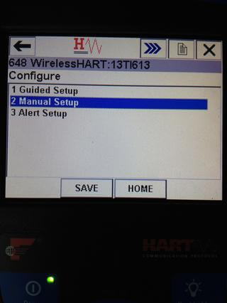
STEP 6 : Go to “Manual Setup”

Wireless HART Transmitter Configuration - 3

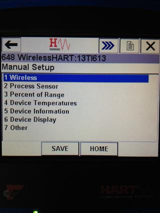
STEP 7 : Go To “Wireless”

Wireless HART Transmitter Configuration - 4

STEP 8 : Go to “Join Device To Network”

Wireless HART Transmitter Configuration - 5

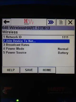
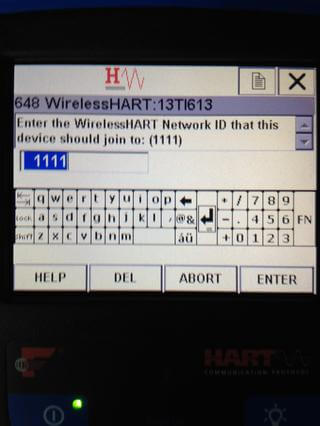
STEP 9 : Key in the Network ID. Then press “Enter”. The ID should be the same as configured in Wireless Gateway.

Wireless HART Transmitter Configuration - 6

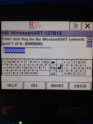
STEP 10 : Key in the 4 parts of the Join Key. Press “Enter” to proceed. The Join Key should be the same as configured in Wireless Gateway.

Wireless HART Transmitter Configuration - 7

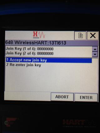
STEP 11 : Press “Enter” to Accept new join key. The device will attempt to connect with the Wireless Gateway. This may take few minutes.

Wireless HART Transmitter Configuration - 8

Note: Depend on the device, the steps may vary. Set to the device lowest burst rate and enable gateway for “Active advertising” to speed up the connection process. The guide is for Rosemount devices

Configuration of Remaining process parameters will be as same as wired HART Transmitters.

Overview : 

In this post, a new wireless device is added to the control system and the measurement it provides is added to a control module.  It is assumed that the wireless gateway has been added to the control system LAN and assigned to the controller.

Step 1: Configure a new wireless device using a field communicator. Enable the burst mode to publish data. Power it on and let it join the wireless network.

Step 2: In the control system explorer view of field devices, open the Reconcile I/O dialog box, find the new device and, drag and drop it to an unused channel.

Step 3: Create a new control module and, assign it to the controller. Add an AI function block and assign its IO_IN to the tag of the channel assigned to the new device.

Step 4: Download the controller.

Step 5: Open the control module online and observe that the value of the AI block periodically updates. The updates come from the burst data of the new device.

Credits : MKR MN

Don't Miss Our Updates
Be the first to get exclusive content straight to your email.
We promise not to spam you. You can unsubscribe at any time.
Invalid email address
You've successfully subscribed !

Continue Reading

Calibrating Level Transmitter with Remote Seals
Calibration Procedure of Voltmeter and Ammeter
How-to do Control Valve Calibration?
Important Terms in Calibration
How to Calibrate Oxygen Analyzer? – O2 Sensor Testing Procedure
What is a Dead Weight Tester?
Share This Article
Facebook Whatsapp Whatsapp LinkedIn Copy Link
Share
Leave a Comment

Leave a Reply Cancel reply

Your email address will not be published. Required fields are marked *

Stay Connected

128.3kFollowersLike
69.1kFollowersFollow
210kSubscribersSubscribe
38kFollowersFollow

Categories

Explore More

Stroke Checking Procedure for GCV, SRV, IGV, and LFBV
How to Calibrate pH Electrode?
Displacer (buoyancy) Level Transmitter Principle, Limitations, Design, Installation & Calibration
Multimeter – What Do Digits and Counts Mean?
Smart Transmitters LRV & URV
Smart Transmitter Calibration Tutorial Part 2
Dissolved oxygen probe calibration procedure
Pressure Transmitter Calibration Procedure

Keep Learning

Closed-tank-DP-Level-Transmitter-with-cleaning-leg-Calibration

Closed tank DP Level Transmitter with cleaning leg Calibration

Impulse Line Pressure Testing Procedure

Impulse Line Pressure Testing Procedure

DP Diaphragm Capillary Seal Level instrument

DP Diaphragm Capillary Seal Level instrument Calibration Procedure

Calibration Instruments

Basics of Calibration

Instrument Calibration Record

How to Create Calibration Records?

The Control Valve Stroke Test Procedure

Control Valve Stroke Test Procedure

Temperature-gauge-calibration

Temperature Sensor calibration procedure

Hybrid Level Transmitter Principle

Hybrid Level Measurement Principle, Selection, Installation, Limitations and Calibration

Learn More

Analytical Standards

Components of Bourdon Tube Pressure Gauge

Components of Bourdon Tube – Questions and Answers

Siemens PLC programming: BCD, Integer, Double Integer, Real

Difference between Induction motor and Synchronous motor

Feedback Characteristics of Control Systems

Controller Components – Part 2 Objective Questions

Analog Demodulators Objective Questions

Analog Demodulators Objective Questions

Laws of Boolean Algebra using Ladder Logic

Laws of Boolean Algebra using Ladder Logic

Technologies for Oxygen Gas Measurement

How to Calibrate Oxygen Analyzer? – O2 Sensor Testing Procedure

Menu

  • About
  • Privacy Policy
  • Copyright

Quick Links

  • Learn PLC
  • Helping Hand
  • Part Time Job

YouTube Subscribe

Follow US
All rights reserved. Reproduction in whole or in part without written permission is prohibited.
Welcome Back!

Sign in to your account

Username or Email Address
Password

Lost your password?