Calibration : Up-tests and Down-tests
Instruments are calibrated to measure the process variables in a fixed range of scale. All instruments are assumed to be Linear if the physical quantity or process variable and the resulting output readings of the instrument have a linear relationship.
The relation between input and output will be either linear, square root, angular, or any custom algorithm. The instrument output has to display the readings in terms of the process variable units.
The manufacturer calibrates by comparing the output of the instrument with respect to a standard input. Having obtained such an instrument, which has been marked and calibrated by the manufacturer, the user has to periodically calibrate the instrument to see whether it is working within the prescribed limits.
In order to calibrate an instrument, we need another standard input which can be measured ten times more accurately than with the instrument under calibration. The standard input is varied within the range of measurement of the instrument to be calibrated.
Based on the standard input and the values obtained from the instrument, one can calibrate the instrument.
Purpose of instrument calibration
Calibration refers to the act of evaluating and adjusting the precision and accuracy of measurement equipment.
Instrument calibration is intended to eliminate or reduce bias in an instrument’s readings over a range for all continuous values.
- Precision is the degree to which repeated measurements under unchanged conditions show the same result
- Accuracy is the degree of closeness of measurements of a quantity to its actual true value.
For this purpose, reference standards with known values for selected points covering the range of interest are measured with the instrument in question.
Then a functional relationship is established between the values of the standards and the corresponding measurements. There are two basic situations:
- Instruments which require correction for bias: The instrument reads in the same units as the reference standards. The purpose of the calibration is to identify and eliminate any bias in the instrument relative to the defined unit of measurement.
- Instruments whose measurements act as surrogates for other measurements: The instrument reads in different units than the reference standards.
Also Read : As-found and As-left Documentation during Calibration
When do instruments need to be calibrated?
- Indicated by manufacturer
- Every instrument will need to be calibrated periodically to make sure it can function properly and safely. Manufacturers will indicate how often the instrument will need to be calibrated.
- Before major critical measurements
- Before any measurements that requires highly accurate data, send the instruments out for calibration and remain unused before the test.
- After major critical measurements
- Send the instrument for calibration after the test helps user decide whether the data obtained were reliable or not. Also, when using an instrument for a long time, the instrument’s conditions will change.
- After an event
- The event here refers to any event that happens to the instrument. For example, when something hits the instrument or any kinds of accidents that might impact the instrument’s accuracy. A safety check is also recommended.
- When observations appear questionable
- When you suspect the data’s accuracy that is due to instrumental errors, send the instrument to calibrate.
- Per requirements
- Some experiments require calibration certificates. As per our plant requirements.
Basic steps for correcting the instrument for bias
The calibration method is the same for both situations stated above and requires the following basic steps:
- Selection of reference standards with known values to cover the range of interest.
- Measurements on the reference standards with the instrument to be calibrated.
- Functional relationship between the measured and known values of the reference standards (usually a least-squares fit to the data) called a calibration curve.
- Correction of all measurements by the inverse of the calibration curve.
Some people mix up field check and calibration. Field check is when two instruments have the same reading; this does not mean they are calibrated; it may be that both instruments are wrong.
Let’s use thermometer as an example; if a thermometer always read .25 degree higher, this error can not be eliminated by taking averages, because this error is constant.
The easiest way to determine if it is accurate and fix it is to send the thermometer to a calibration laboratory. Another way to reveal constant errors is to have one or more similar thermometers.
One thermometer is used and then replaced by another thermometer. If readings are divided among two or more thermometers, inconsistencies among the thermometers will ultimately be revealed.
Also Read : Smart Transmitter Calibration
Calibration : Up-tests and Down-tests
It is not uncommon for calibration tables to show multiple calibration points going up as well as going down, for the purpose of documenting hysteresis and deadband errors.
Note the following example, showing a transmitter with a maximum hysteresis of 0.313 % (the offending data points are shown in bold-faced type):
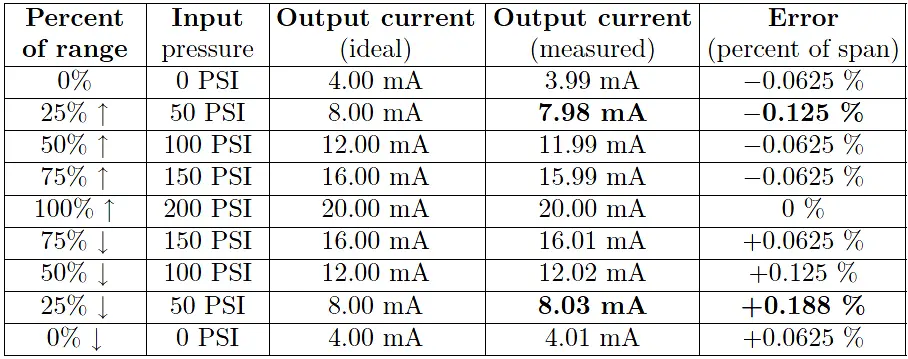
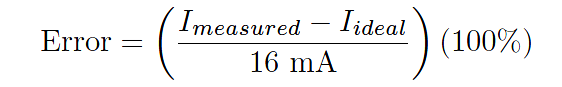
Note again how error is expressed as either a positive or a negative quantity depending on whether the instrument’s measured response is above or below what it should be under each condition. The values of error appearing in this calibration table, expressed in percent of span, are all calculated by the following formula:
In the course of performing such a directional calibration test, it is important not to overshoot any of the test points. If you do happen to overshoot a test point in setting up one of the input conditions for the instrument, simply “back up” the test stimulus and re-approach the test point from the same direction as before.
Unless each test point’s value is approached from the proper direction, the data cannot be used to determine hysteresis/deadband error.
Also Read : Error sources creating uncertainty in Calibration
Reference : chem.libretexts.org
Credits : by Tony R. Kuphaldt – under Creative Commons Attribution 4.0 License


If digital pressure gauge is calibrated in bars. May is use the same gauge for values in kg/cm2.