Inst ToolsInst ToolsInst Tools
  • Courses
  • Automation
    • PLC
    • Control System
    • Safety System
    • Communication
    • Fire & Gas System
  • Instrumentation
    • Design
    • Pressure
    • Temperature
    • Flow
    • Level
    • Vibration
    • Analyzer
    • Control Valve
    • Switch
    • Calibration
    • Erection & Commissioning
  • Interview
    • Instrumentation
    • Electrical
    • Electronics
    • Practical
  • Q&A
    • Instrumentation
    • Control System
    • Electrical
    • Electronics
    • Analog Electronics
    • Digital Electronics
    • Power Electronics
    • Microprocessor
  • Request
Search
  • Books
  • Software
  • Projects
  • Process
  • Tools
  • Basics
  • Formula
  • Power Plant
  • Root Cause Analysis
  • Electrical Basics
  • Animation
  • Standards
  • 4-20 mA Course
  • Siemens PLC Course
Reading: Thermocouple Construction
Share
Font ResizerAa
Inst ToolsInst Tools
Font ResizerAa
  • Courses
  • Design
  • PLC
  • Interview
  • Control System
Search
  • Courses
  • Automation
    • PLC
    • Control System
    • Safety System
    • Communication
    • Fire & Gas System
  • Instrumentation
    • Design
    • Pressure
    • Temperature
    • Flow
    • Level
    • Vibration
    • Analyzer
    • Control Valve
    • Switch
    • Calibration
    • Erection & Commissioning
  • Interview
    • Instrumentation
    • Electrical
    • Electronics
    • Practical
  • Q&A
    • Instrumentation
    • Control System
    • Electrical
    • Electronics
    • Analog Electronics
    • Digital Electronics
    • Power Electronics
    • Microprocessor
  • Request
Follow US
All rights reserved. Reproduction in whole or in part without written permission is prohibited.
Inst Tools > Blog > Temperature Measurement > Thermocouple Construction

Thermocouple Construction

Last updated: May 22, 2018 2:49 pm
Editorial Staff
Temperature Measurement
No Comments
Share
4 Min Read
SHARE

A thermocouple is constructed of two dissimilar metal wires joined at one end. When one end of each wire is connected to a measuring instrument, the thermocouple becomes a sensitive and highly accurate measuring device.

Thermocouples may be constructed of several different combinations of materials. The performance of a thermocouple material is generally determined by using that material with platinum.

The most important factor to be considered when selecting a pair of materials is the “thermoelectric difference” between the two materials. A significant difference between the two materials will result in better thermocouple performance.

Thermocouple Material Characteristics

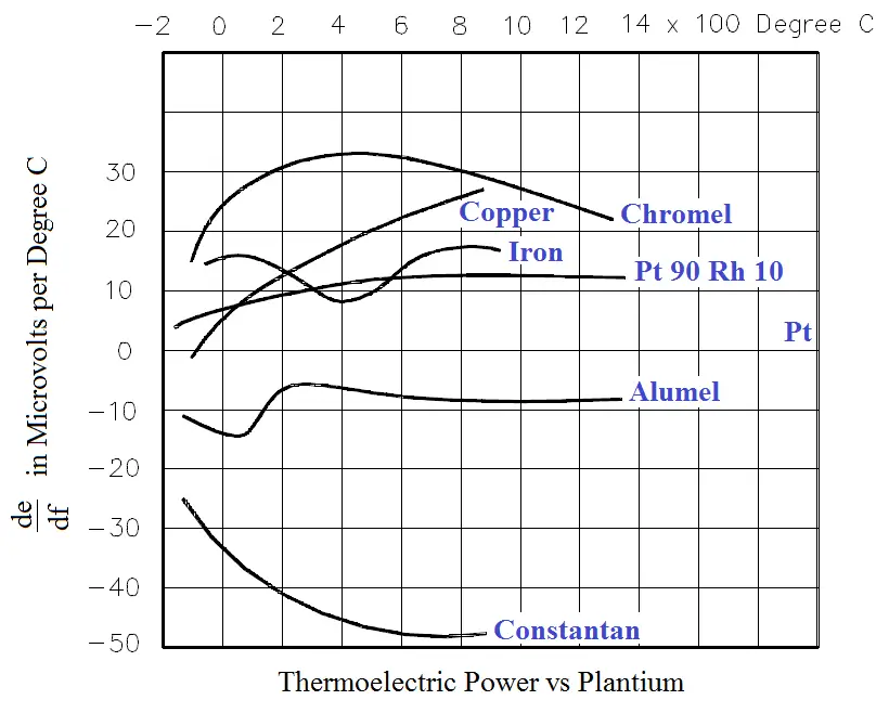
Figure 1 illustrates the characteristics of the more commonly used Thermocouple materials when used with platinum.

Other materials may be used in addition to those shown in Figure 1. For example: Chromel- Constantan is excellent for temperatures up to 2000°F; Nickel/Nickel-Molybdenum sometimes replaces Chromel-Alumel; and Tungsten-Rhenium is used for temperatures up to 5000°F. Some combinations used for specialized applications are Chromel-White Gold, Molybdenum-Tungsten, Tungsten-Iridium, and Iridium/Iridium-Rhodium.

Figure 2 shows the Internal Construction of a Typical Thermocouple. The leads of the thermocouple are encased in a rigid metal sheath. The measuring junction is normally formed at the bottom of the thermocouple housing. Magnesium oxide surrounds the thermocouple wires to prevent vibration that could damage the fine wires and to enhance heat transfer between the measuring junction and the medium surrounding the thermocouple.

Thermocouple Construction

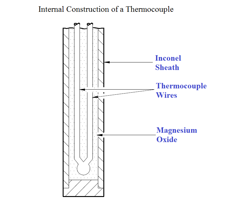
Figure 2 Internal Construction of a Typical Thermocouple

Thermocouple Operation

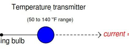
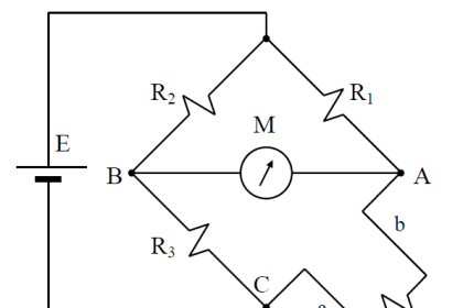
Thermocouples will cause an electric current to flow in the attached circuit when subjected to changes in temperature. The amount of current that will be produced is dependent on the temperature difference between the measurement and reference junction; the characteristics of the two metals used; and the characteristics of the attached circuit. Figure 3 illustrates a simple thermocouple circuit.

Thermocouple Circuit

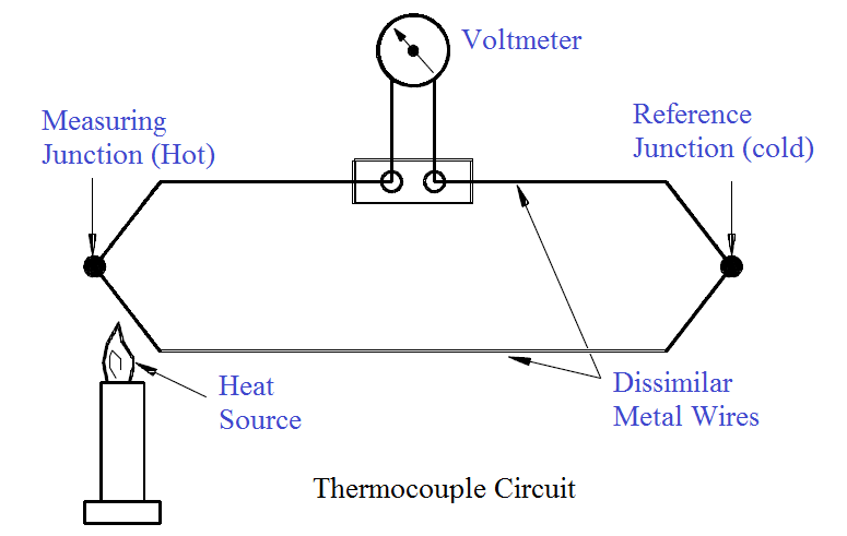
Figure 3 Simple Thermocouple Circuit

Heating the measuring junction of the thermocouple produces a voltage which is greater than the voltage across the reference junction. The difference between the two voltages is proportional to the difference in temperature and can be measured on the voltmeter (in millivolts). For ease of operator use, some voltmeters are set up to read out directly in temperature through use of electronic circuity.

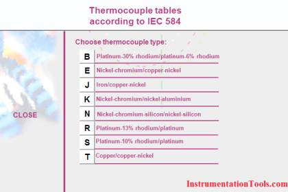
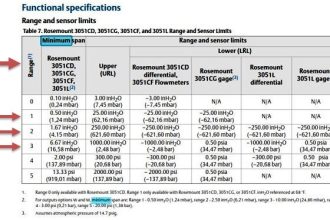
Other applications provide only the millivolt readout. In order to convert the millivolt reading to its corresponding temperature, you must refer to tables like the one shown in Figure 4. These tables can be obtained from the thermocouple manufacturer, and they list the specific temperature corresponding to a series of millivolt readings.

Thermocouple Voltage in Absolute Millivolts

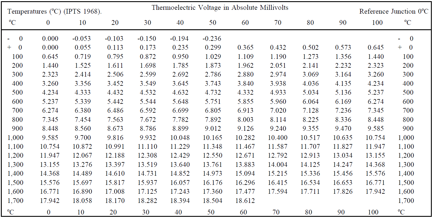
Figure 4 Temperature-vs-Voltage Reference Table

Summary

Thermocouples are summarized below.

  • A thermocouple is constructed of two dissimilar wires joined at one end and encased in a metal sheath.
  • The other end of each wire is connected to a meter or measuring circuit.
  • Heating the measuring junction of the thermocouple produces a voltage that is greater than the voltage across the reference junction.
  • The difference between the two voltages is proportional to the difference in temperature and can be measured on a voltmeter.
Don't Miss Our Updates
Be the first to get exclusive content straight to your email.
We promise not to spam you. You can unsubscribe at any time.
Invalid email address
You've successfully subscribed !

Continue Reading

Introduction to RTDs
Resistance Temperature Detectors (RTD) Sources of Error
RTD Questions and Answers
Thermocouple Properties, Temperature Ranges, Element Construction
How Does an Infrared Thermometer Work?
Use of Temperature Transmitters instead of Direct Wiring
Share This Article
Facebook Whatsapp Whatsapp LinkedIn Copy Link
Share
Leave a Comment

Leave a Reply Cancel reply

Your email address will not be published. Required fields are marked *

Stay Connected

128.3kFollowersLike
69.1kFollowersFollow
210kSubscribersSubscribe
38kFollowersFollow

Categories

Explore More

Pyrometers Handbook
Temperature Error of 2-Wire, 3-Wire & 4-Wire RTD
Disadvantages of Resistance Temperature Detectors
Functions of Temperature Detectors
Why have been limits imposed on the frequency ratio for thermowells?
Types of Thermocouples
Thermocouple Calculations
Important Factors for Thermocouple Selection

Keep Learning

field-mounted thermocouple

Thermocouple Extension Wires

Thermocouple Wiring Diagram

Basics of Thermocouples and RTD

Effect of Lead Wire Resistance on RTD

Effect of Lead Wire Resistance on RTD

Temperature Measurement Objective Questions

Temperature Measurement Objective Questions

Thermocouples Calibration Errors

Thermocouples Sources of Error

Temperature Sensors Questions

Questions on Thermocouple and Pyrometer

Filled-bulb Temperature Measurement

Filled-bulb Temperature Sensors

Installation Precautions of Thermocouple and RTD

Installation Precautions of Thermocouple and RTD

Learn More

inductance transducer

Inductance Type Pressure Transducers Principle

Thermocouple Temperature Measurements Errors

Thermocouple Temperature Measurement Errors

advantages-of-suspension-insulators-and-pin-type-insulators

Advantages of Suspension Insulators and Pin type Insulators

BLDC Motor Vs AC Induction Motor

Ion Analyzers Questions and Answers

Ammonia and Fluoride Electrode Questions & Answers

Power Systems Questions & Answers

Power Systems MCQ Series 19

RSlogix 500 to communicate with Excel

How to Communicate with Excel from RsLinx?

absorption-type optical analyzer

Absorption Type Optical Analyzer

Menu

  • About
  • Privacy Policy
  • Copyright

Quick Links

  • Learn PLC
  • Helping Hand
  • Part Time Job

YouTube Subscribe

Follow US
All rights reserved. Reproduction in whole or in part without written permission is prohibited.
Welcome Back!

Sign in to your account

Username or Email Address
Password

Lost your password?