Inst ToolsInst ToolsInst Tools
  • Courses
  • Automation
    • PLC
    • Control System
    • Safety System
    • Communication
    • Fire & Gas System
  • Instrumentation
    • Design
    • Pressure
    • Temperature
    • Flow
    • Level
    • Vibration
    • Analyzer
    • Control Valve
    • Switch
    • Calibration
    • Erection & Commissioning
  • Interview
    • Instrumentation
    • Electrical
    • Electronics
    • Practical
  • Q&A
    • Instrumentation
    • Control System
    • Electrical
    • Electronics
    • Analog Electronics
    • Digital Electronics
    • Power Electronics
    • Microprocessor
  • Request
Search
  • Books
  • Software
  • Projects
  • Process
  • Tools
  • Basics
  • Formula
  • Power Plant
  • Root Cause Analysis
  • Electrical Basics
  • Animation
  • Standards
  • 4-20 mA Course
  • Siemens PLC Course
Reading: Calculate Flow Transmitter Output Current
Share
Font ResizerAa
Inst ToolsInst Tools
Font ResizerAa
  • Courses
  • Design
  • PLC
  • Interview
  • Control System
Search
  • Courses
  • Automation
    • PLC
    • Control System
    • Safety System
    • Communication
    • Fire & Gas System
  • Instrumentation
    • Design
    • Pressure
    • Temperature
    • Flow
    • Level
    • Vibration
    • Analyzer
    • Control Valve
    • Switch
    • Calibration
    • Erection & Commissioning
  • Interview
    • Instrumentation
    • Electrical
    • Electronics
    • Practical
  • Q&A
    • Instrumentation
    • Control System
    • Electrical
    • Electronics
    • Analog Electronics
    • Digital Electronics
    • Power Electronics
    • Microprocessor
  • Request
Follow US
All rights reserved. Reproduction in whole or in part without written permission is prohibited.
Inst Tools > Blog > Flow Measurement > Calculate Flow Transmitter Output Current

Calculate Flow Transmitter Output Current

A flow transmitter is ranged 0 to 350 GPM, 4-20 mA output, direct-responding. Calculate Flow Transmitter Output 4-20mA Current for 204 GPM.

Last updated: October 31, 2023 12:33 pm
Editorial Staff
Flow Measurement Formulas
2 Comments
Share
2 Min Read
SHARE

A  flow transmitter ranges from 0 to 350 GPM with 4 to 20 mA output, direct-responding. Calculate the current signal value at a flow rate  of 204 GPM.
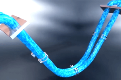
Contents
Flow TransmitterFlow Transmitter Calculations

Flow Transmitter

Flow Transmitter Calculations

We are solving this problem using the standard 4-20mA Conversion Formula. Click here for the formula

One way we could solve for the amount of signal current is to convert the flow value of 204.

GPM  into a ratio of the flowmeter’s full-flow value,  then apply the same formula we used in the previous example relating percentage to milliamps.

Converting the flow rate into a “per unit” ratio is a matter of simple division since the flow measurement range is zero-based:

Flow Transmitter 4-20 mA formula

Therefore,  the transmitter should output a PV signal of 13.3 mA at a flow rate of 204 GPM.

Flow Transmitter Calculations

An alternative approach is to set up a linear equation specifically for this flowmeter given its measurement range (0 to 350 GPM)  and output signal range (4 to 20 mA).

We will begin this process by sketching  a simple graph relating flow rate to current:

flow transmitter formula

Therefore,  the transmitter should output a PV signal of 13.3 mA at a flow rate of 204 GPM.

We can also solve the problem using a direct formula. Click here for the formula

If you liked this article, then please subscribe to our YouTube Channel for Instrumentation, Electrical, PLC, and SCADA video tutorials.

You can also follow us on Facebook and Twitter to receive daily updates.

Read Next:

  • Flow Control Loop Controller
  • Variable Area Flow Meters
  • Linear to Square Root Extraction
  • PV to Percentage Conversion
  • Closed Tank Level Calculations
Don't Miss Our Updates
Be the first to get exclusive content straight to your email.
We promise not to spam you. You can unsubscribe at any time.
Invalid email address
You've successfully subscribed !

Continue Reading

What is an Insertion Flow Meter? – Types, Principle, Advantages
Basics of Restriction Orifice (RO) – Types, Applications, Standards
Raw Counts to Engineering Units : Conversion Formula
Reasons to Calibrate Different Types of Flow Meters
Basics of Orifice Plates
Target Flow Meter – Working Principle, Advantages, Disadvantages
Share This Article
Facebook Whatsapp Whatsapp LinkedIn Copy Link
Share
2 Comments
  • Faran says:
    October 2, 2015 at 7:24 pm

    Also Another Simple way to calculate:
    Signal = 4 – 20 mA..
    So Signal varies between 16 mA
    So Each gallon tends to have (16/350)= 0.046 mA
    So 204 Gallon will make (0.0457 * 204) = 9.33 mA
    Hence Output signal will be 4 mA + 9.33 mA = 13.33 mA

    Reply
  • aiyaz says:
    November 22, 2016 at 7:33 am

    how calibrate a ff type flow transmitter ABB 2600T range is 53.39mbar and out showing 5000m3/H how calculate plz gv reply on transmitter showing 53.39 m baar and on data sheet showing calibration range 5000 m3/hm confuse

    Reply

Leave a Reply Cancel reply

Your email address will not be published. Required fields are marked *

Stay Connected

128.3kFollowersLike
69.1kFollowersFollow
210kSubscribersSubscribe
38kFollowersFollow

Categories

Explore More

Flow Transmitter Rangeability
Types of Variable Area Flow Meters
How to Select a Rotameter? – Parameters and Applications
What is a Paddle Wheel Flow Meter?
Siemens Pressure Transmitter with Remote Seals Calculations
Orifice Plate Questions and Answers
Flow Standards
DP Level Transmitter Elevation and Suppression Corrections

Keep Learning

Transit Time flow meter Theory

Transit Time Flow Meter Principle

DP transmitter

Square-root characteristics of Differential Pressure Flow Meters

Lobed Impeller Flow Meters Working Principle

Lobed Impeller Flow Meters Working Principle

Orifice Plate Flow Requirements

What are the Orifice Plate Flow Requirements?

Weigh feeders Principle

What is a Weigh Feeder?

Types of Flow Meters MCQ - Instrumentation and Control

Types of Flow Meters MCQ – Instrumentation and Control

Ultrasonic Flowmeters Principle

Factors Affecting the Performance of Ultrasonic Flow Meters

flow Nozzle

Flow Nozzle Principle, Advantages, Disadvantages, Applications

Learn More

Piezo Electric Transducers Objective Questions

Piezo Electric Transducers Objective Questions

Process Air Compressor Overhauls Eliminated

Process Air Compressor too Frequent & too Lengthy Overhauls Eliminated

Two-Liquid Manometer Principle

Two-Liquid Manometer Principle

On Delay Timer TON in Tia Portal

Timers in PLC Programming – Siemens Tia Portal Tutorials

gauge’s bourdon tube

Pressure Gauges : Remote and Chemical Seals

Bimetallic Thermometer

Bimetallic Thermometer

Valve Safety Factor

Valve Safety Factor

pressure gauge snubber

Pressure Gauge Snubbers

Menu

  • About
  • Privacy Policy
  • Copyright

Quick Links

  • Learn PLC
  • Helping Hand
  • Part Time Job

YouTube Subscribe

Follow US
All rights reserved. Reproduction in whole or in part without written permission is prohibited.
Welcome Back!

Sign in to your account

Username or Email Address
Password

Lost your password?