Inst ToolsInst ToolsInst Tools
  • Courses
  • Automation
    • PLC
    • Control System
    • Safety System
    • Communication
    • Fire & Gas System
  • Instrumentation
    • Design
    • Pressure
    • Temperature
    • Flow
    • Level
    • Vibration
    • Analyzer
    • Control Valve
    • Switch
    • Calibration
    • Erection & Commissioning
  • Interview
    • Instrumentation
    • Electrical
    • Electronics
    • Practical
  • Q&A
    • Instrumentation
    • Control System
    • Electrical
    • Electronics
    • Analog Electronics
    • Digital Electronics
    • Power Electronics
    • Microprocessor
  • Request
Search
  • Books
  • Software
  • Projects
  • Process
  • Tools
  • Basics
  • Formula
  • Power Plant
  • Root Cause Analysis
  • Electrical Basics
  • Animation
  • Standards
  • 4-20 mA Course
  • Siemens PLC Course
Reading: Calculate Control Valve Stem Position
Share
Notification Show More
Font ResizerAa
Inst ToolsInst Tools
Font ResizerAa
  • Courses
  • Design
  • PLC
  • Interview
  • Control System
Search
  • Courses
  • Automation
    • PLC
    • Control System
    • Safety System
    • Communication
    • Fire & Gas System
  • Instrumentation
    • Design
    • Pressure
    • Temperature
    • Flow
    • Level
    • Vibration
    • Analyzer
    • Control Valve
    • Switch
    • Calibration
    • Erection & Commissioning
  • Interview
    • Instrumentation
    • Electrical
    • Electronics
    • Practical
  • Q&A
    • Instrumentation
    • Control System
    • Electrical
    • Electronics
    • Analog Electronics
    • Digital Electronics
    • Power Electronics
    • Microprocessor
  • Request
Follow US
All rights reserved. Reproduction in whole or in part without written permission is prohibited.
Inst Tools > Blog > Control Valves > Calculate Control Valve Stem Position

Calculate Control Valve Stem Position

Last updated: April 20, 2019 1:18 pm
Editorial Staff
Control Valves Formulas
6 Comments
Share
1 Min Read
SHARE

An electronic  loop controller  outputs  a signal of 8.55 mA to a direct-responding control valve (where 4 mA is shut and 20 mA is wide open).

How far open should the control  valve be at this MV signal level?

Calculate Control Valve Stem Position
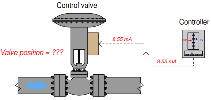
Calculate Control Valve Stem Position

We are solving this problem using standard 4-20mA conversion Formula. Click here for formula

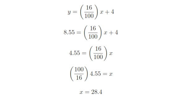
To solve for percentage of stem travel (x) at 8.55 milliamps of signal current (y), we may use the linear equation developed previously to predict  current in milliamps (y) from signal value in percent (x):

Valve Position Find

Therefore, we should expect the valve to be 28.4% open at an applied MV signal of 8.55 milliamps.

We can also solve the problem using direct formula. Click here for formula

Also Read: Instrumentation Formulas
Don't Miss Our Updates
Be the first to get exclusive content straight to your email.
We promise not to spam you. You can unsubscribe at any time.
Invalid email address
You've successfully subscribed !

Continue Reading

Relative Flow Capacity of a Valve
Valve Functions and Basic Parts of Valve
What is Reducing Valve ?
Control Valves Leakage Classifications
Control Valve Air Lock Relay Working Principle
Formula to Calculate 3-15psi from 4-20mA Current
Share This Article
Facebook Whatsapp Whatsapp LinkedIn Copy Link
Share
6 Comments
  • Suresh says:
    November 17, 2015 at 6:50 am

    Very good

    Reply
  • shaik says:
    January 12, 2016 at 1:49 pm

    Very helpful ?

    Reply
  • Ismail says:
    January 1, 2017 at 4:03 pm

    Very very helpful and too much useful

    Reply
  • Jabulani says:
    September 17, 2017 at 4:51 pm

    Thank you very much for sharing your vast knowledge with us.

    Reply
  • AMIT KUMAR says:
    October 16, 2024 at 4:19 pm

    Where did these 16 values ​​come from?

    Reply
  • AMIT KUMAR says:
    October 16, 2024 at 4:21 pm

    Y% = X-4
    ——- .100
    16

    Where did these 16 values ​​come from

    Reply

Leave a Reply Cancel reply

Your email address will not be published. Required fields are marked *

Stay Connected

128.3kFollowersLike
69.1kFollowersFollow
210kSubscribersSubscribe
38kFollowersFollow

Categories

Explore More

Control Valve Trim Characteristics
Locked Open (LO) and Locked Closed (LC) Valves
Control Valve Passing Problem after Overhauling Job
What is Valve Packing ?
Solenoid Valve Selection Criteria
How Ball Valves Work ?
How to Select Control Valve Failure Mode
What is Partial Stroke Test?

Keep Learning

Control Valves Flow Direction

Control Valve Flow Direction

Tilting Disk Check Valve Principle

What is Tilting Disk Check Valve ?

4-20ma-formulas-and-examples

4-20mA Formulas and Examples

Valve Safety Factor

Valve Safety Factor

Valves Pressure Loss - Questions and Answers

Valves Pressure Loss – Questions and Answers

Safety Relief Valve

Safety Relief Valve Quiz: Test Your Knowledge

Control Valve pressure recovery

What is Control Valve Flashing ?

Valve Leakage Tests

Types of Valve Leakage Tests

Learn More

Sticker machine with weighing PLC logic

Product Sticker Machine with Weighing PLC Program

Direct & reverse actions control valve

Direct Acting Control Valves & Reverse Acting Control Valves

DCS Vs PLC

DCS versus PLC Architecture

PTC NTC Thermistors Comparation

Thermistor Working Principle

Instruments Tapping Points

Instruments Tapping Points – Common versus Individual

Limit, Selector, and Override controls

Limit, Selector, and Override controls

Ratio control

What is Ratio Control ?

Top 100 Power Systems Projects

Top 100 Power Systems Projects – Electrical Engineering

Menu

  • About
  • Privacy Policy
  • Copyright

Quick Links

  • Learn PLC
  • Helping Hand
  • Part Time Job

YouTube Subscribe

Follow US
All rights reserved. Reproduction in whole or in part without written permission is prohibited.
Welcome Back!

Sign in to your account

Username or Email Address
Password

Lost your password?