Thyristor is a three terminal device with four layers of alternating P and N type material (three P-N junctions). The three terminals are Anode, Cathode and Gate.
- The Thyristor is mentioned as Silicon Controlled Rectifier (SCR) as it is made up of silicon and working as controlled rectifier.
- The thyristor is inherently a slow switching device compared to BJTs or MOSFETs because of the long carrier lifetimes used for low on-state losses and because of the large amount of stored charge.
- It is therefore normally used at lower switching frequencies.
- It has large reverse-recovery currents.
Types of Thyristors:
Unidirectional thyristor:
- The thyristors which conduct in forward direction only are known as unidirectional thyristors
- Example: SCR- Silicon Controlled Rectifier

LASCR-Light Activated Silicon Controlled Rectifier
Bidirectional Thyristor:
- The thyristors which can conduct in forward as well as in reverse direction are known as bidirectional thyristor
- Ex: TRIAC – TRIode AC switch
Triggering Devices:
- The devices which generate a control signal to switch the device from non-conducting to conducting state is called as triggering device.
- Ex: Diode AC Switch-DIAC,
UJT – UniJunction Transistor
SUS – Silicon Unilateral Switch
SBS – Silicon Bilateral Switch
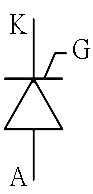
Symbol:
The thyristor symbol contains the traditional diode symbol with a gate terminal.
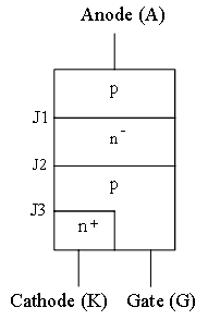
Structure:
The thyristor has a unique four layer construction of alternating P-type and N-type regions. It is given below:
The SCR looks like two PNP transistor connected in a back to back manner.
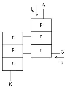
It can be understood with the reference of above figure.
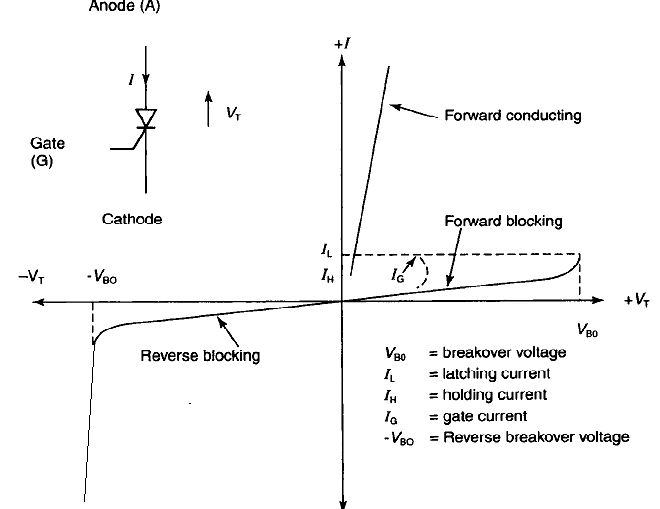
The operation and VI characteristic of Thyristor:
The operation of the SCR is explained by the help of four modes.
- Forward Blocking Mode
- Forward Conducting Mode
- Reverse Blocking Mode
- Reverse Conducting Mode

Forward Blocking Mode [VAK = +ve & VG = 0]
- When a positive voltage is applied to anode with respect to cathode, the junctions J1 and J3 are forward biased, junction J2 is reverse biased.
- The SCR is in Forward Blocking state. At this time the Gate signal is not applied.
- A depletion layer is formed in junction J2 and no current flows from anode to cathode.
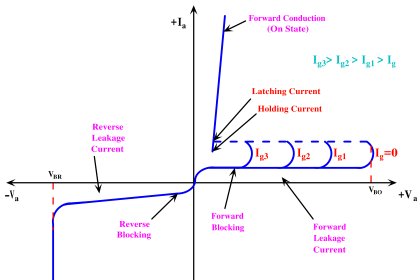
- As shown in VI Characteristic, a small amount of current called forward leakage current flows through the device.
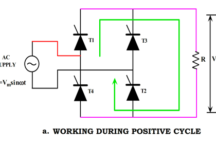
Forward Conducting Mode [VAK = +ve & VG = +ve]
- When the small amount of positive voltage is applied to gate terminal, while positive voltage is applied to anode with respect to cathode, the junction J3 becomes forward biased.
- So the SCR acts as a closed switch and conducts a large value of forward current with small voltage drop.
- With the application of gate signal the SCR changed from forward blocking state to forward conducting state. It is called as latching.
- Without gate signal SCR changed from forward blocking state to forward conducting state at forward breakdown voltage (Vfbd).
- When the gate signal value is increased, the latching happens for low Vakvoltages as mentioned in the figure.
- In the presence of forward current (i.e. after the thyristor is turned on by a suitable gate voltage) it will not turn off even after the gate voltage has been removed. The thyristor will only turn off when the forward current drops below holding current.
- The holding current is defined as the minimum current required to hold the SCR in the forward conduction state.
Reverse Blocking Mode [VAK = -ve]
- When a negative voltage is applied to anode with respect to cathode, the junctions J1 and J3 are reverse biased, but the junction J2 is forward biased.
- The SCR is in its reverse blocking state. ie, it acts as an open switch.
- As shown in figure a small amount of reverse leakage current flows through the device.
Reverse Conducting Mode:
- As the reverse voltage is further increased, at the reverse breakdown voltage(VBR) Avalanche breakdown occurs at junction J1 and J3.
- SCR acts as a closed switch in reverse direction
- A large current gives more losses in SCR, dissipating in the form of heat, thereby damaging the SCR.
The SCR switching characteristics explains about the turn-on and turn-off loss of the device which is very important factor to be considered for the selection of the device.
The turn ON process of Thyristor is called as Triggering. Click here to know more about various Triggering methods…
The turn Off process of SCR is known as commutation. Click here to know more about SCR Turn OFF methods…
The SCR should be operated within the specified ratings. Click here to know more about Various SCR Protections…
Parameters of Thyristors:
Latching Current(IL):
It is the minimum anode current required to switch(latch) the SCR from OFF state t ON state.
Holding Current(IH):
It is the minimum anode current required to hold the SCR in ON state.
(OR)
It is the minimum current below which the device will move from ON state to OFF state.
Peak Reverse Voltage:
It is the maximum voltage that can be applied across the SCR in reverse biased condition.
Peak Inverse Voltage:
It is the maximum voltage which the device can safely withstand in its OFF state.
ON State Voltage:
The voltage which appears across the device during it’s ON state is known as it’s ON state Voltage.
Rate of rise of voltage dv/dt:
The rate at which the voltage across the device rises without triggering the device is known as its rate of rise of voltage.
Current Rating:
The current carrying capacity of the device is known as its current rating.
Merits of SCR:
- SCRs with high voltage and current ratings are available.
- On state losses in SCRs are reduced.
- Very small amount of gate drive is required since SCR is a regenerative device.
Demerits of SCR:
- Gate has no control after the SCR is turned ON.
- External circuits are required to turn OFF the SCR.
- Operating frequencies are very low.
- Snubber circuits are required for dv/dt protection.
Applications of SCR:
- SCRs are used for controlled rectifiers.
- AC regulators, lighting and heating applications.
- DC motor drives large power supplies and electronic circuit breakers