Final control elements used in Safety Instrumented System (SIS) application shall be carefully engineered to meet the stringent requirements. As these valves are operated based on the safety requirements per LOPA, they’re termed as Automated Block Valve (ABV).
Usually, these valves play a critical role in isolating the process from any hazardous events, hence the valves need to meet the SIS design requirements and satisfy the testing needs.
Automated Block Valve
The basic characteristics of Automated Block Valves (ABV) are as follows
- Automated Block valves are of Quarter-turn type on/off valve assemblies with pneumatic actuation
- Valve designs are Ball / Butterfly valves / Plug valves in some cases.
- Quarter-turn Valve Styles – Metal seat, Soft seat, Full bore, Reduced bore & Cavity Relief
- Valve Leakage Rate: the valves seat leakage is a critical parameter and it has to meet the design requirement by API-598 or IEC 60534-4 Class V, VI for metal seated ball valves
- Actuators are of Rack & Pinion or Scotch Yoke type.
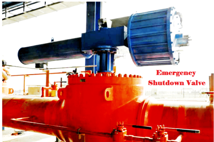
Ball Valve
A ball valve is a type of quarter-turn valve which uses a hollow and pivoting ball to control flow through it.
The valve turns full open when the ball’s hollow portion is parallel to the pipeline with the flow and the valve turns closed when the ball’s hollow portion is perpendicular to the pipeline (which is a 90-degrees turn).
The valve can be operated automatically with a pneumatic/electric actuator or manually by the valve handle.
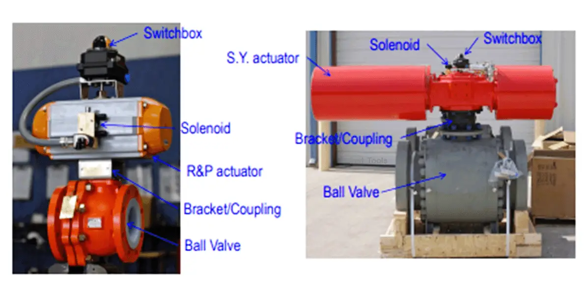
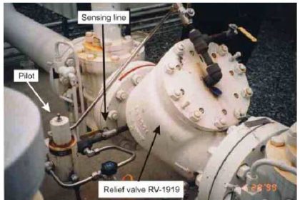
A typical picture of Quarter-turn Ball valve assemblies with pneumatic actuation is shown above.
Butterfly Valve
The butterfly valve has a disc and shaft arrangement, with the rotation of the valve disc controlling the fluid flow. In the closed position, the disc seats along the pipe bore, thus blocking the flow through the valve. Whereas in the open position, the disc is oriented perpendicular to the flow direction to allow flow.
There are 3 types viz.
- Zero offset,
- Double offset &
- Triple offset butterfly valve.
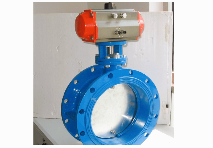
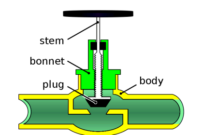
Typical schematic of Butterfly valve
SIS Valve (ABV) Application Characteristics
SIS Valves‘ performance is based on the below factors:
- Fluid Medium
- Process Data parameters
- Design Conditions
- Fluid Properties
- Flow Direction
- Pressure / Temperature rating (Pipe Specification – pressure class, rating)
Application Specific Requirements
The below parameters decide the type of valve to be chosen in SIS applications.
- Cycle Frequency
- Open/Closing Time (travel time)
- Water hammering
- SIL classification (SIL 1/2/3)
- Fail Action
- Fire Safe/Fire Retardant
- Fugitive Emission Requirements
- Tightness Class requirement
SIS Valve (ABV) selection is based on the Application characteristic and Specific requirements for the respective applications.
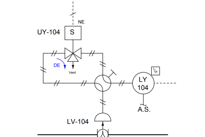
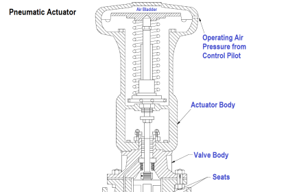
Pneumatic on/off Valve Actuator Sizing
Actuator sizing is very vital for the safe and fast response of SIS valves.
- Required valve torque values
- Available actuator output torque
- Available air supply pressure
Actuator output torque > Required valve torque
Actuator output torque < Max allowable stem torque
Valve Data Required for Actuator Sizing
Below parameters are required to be provided by the Valve manufacturer to the Actuator manufacturer for designing a suitable actuator for a particular valve.
- Valve torque
- Net break out the torque for the available shut off pressure
- Torque factors: Running torque; Break away from open torque: Reseating torque
- Torque correction factors: Application characteristics like particles, application process temperature
- Frequency of operations etc
- Maximum Allowable Stem Torque (MAST)
- Travel time requirements
Actuator Data Required to do the Valve Sizing
The below parameters are required to be provided by the Actuator manufacturer to the Valve manufacturer for designing a suitable actuator for a particular valve.
- Air supply pressure related: Air start torque; Air end torque’ Air running torque
- Spring related: Spring supply pressure related: Spring start torque; Spring end torque; Spring running torque
- Adjustment factors for high/low-temperature executions
- Intermediate travel stop (if any) – Break to close torque
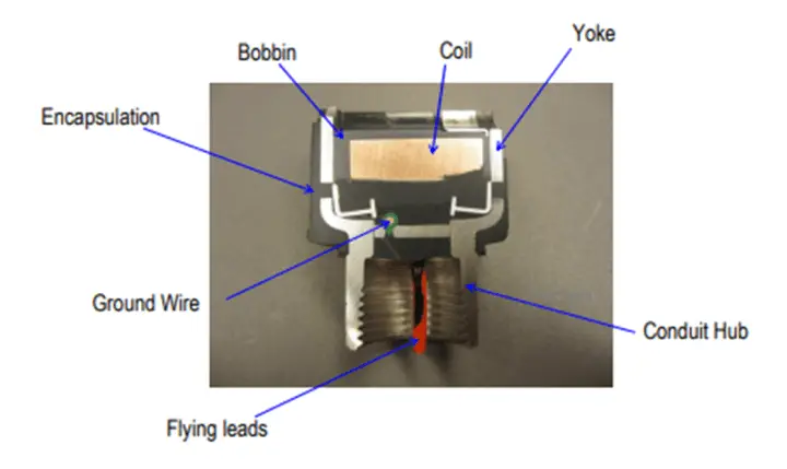
Solenoid Valve
Type of solenoid valve in SIS valve application also plays a vital role Default:
Namur type solenoid – Breather function: keeps spring chamber actuator clean
Pipe mounted solenoid – re-breather block
3/2-way for single acting
5/2-way for double acting
Types of Solenoid Valves
Direct Operated valves require Higher power consumption (>7 Watt), Bigger Cv-values (> ~5.0), and hence more reliable.
Pilot Operated valves have Lower power consumption (< 2 Watt), Smaller Cv values (< ~5.0), and current consumption is also very less, More vulnerable to non-clean air supply filters in air supply.
Solenoid valve coil assembly (ref figure)
Switch box
The type of switch/ switch box shall be according to the actuator style to have better assembling and ease of maintenance.
Switch types
Proximity type switch (non-contact switch)
Reed Switch: switch activated by an external magnetic field
Inductive Switch: detect magnetic loss due to eddy currents that are generated on a conductive surface by an external magnetic field.
Of all the above types Non-contact type proximity type switch is most preferred for SIS applications.
Mechanical types of switches shall never be used in SIS.
Conclusion
We must understand the type of valve, actuator, solenoid valve, switch, and accessories such as Air Filter/Regulator, Booster relays to be selected with a thorough understanding of the process fluid/gas application and valve response, leakage requirement.