“Surge” phenomenon is common in Centrifugal compressors. It is an operating point where downstream pressure of compressor discharge rapidly increases due to a decrease in flow demand from the compressor outlet. Since compressor keeps running additional build up pressure has to transfer to atmosphere or suction side of compressor.
This situation arises when there is an emergency shutdown or downstream consumers are not available.
Generally, surge cycles are at a rate of 0.3s to 3s per Surge cycles, during surges compressor vibrates, the temperature rises, and causes noise.
To prevent the compressor from surges, a reversal of flow, process instability, and compressor damage, the compressor discharge flow is diverted to compressor suction via an anti-surge / recycle control valve.
There is a change in the compressor operating point (which is moving towards surge line). During the extreme condition, the compressor has to run in minimum flow condition (keep running without any trip)
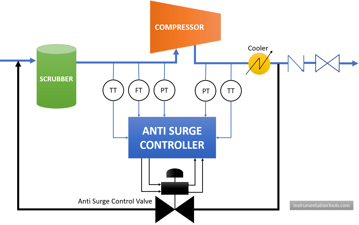
The basic function of the anti-surge controller and control valve is to maintain minimum flow through compressor and handle the surges.
Measurement of compressor suction pressure, suction temperature, suction flow, discharge pressure, and discharge temperature is important to calculate proximity to surge line.
Anti Surge Controller
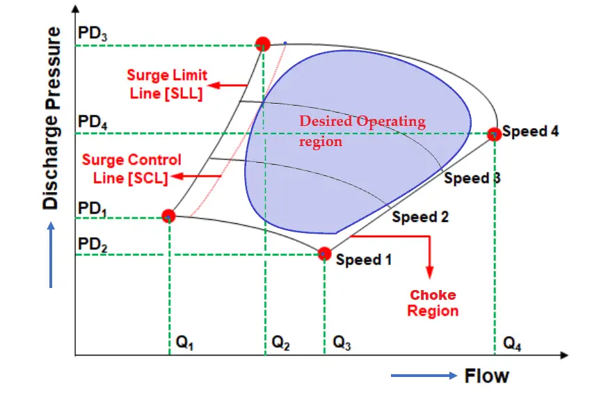
If you correlate the compressor head (Pressure) vs flow curve, you will notice that minimum flow corresponds to higher head, and maximum flow corresponds to minimum head pressure, for a given one speed.
The operating limits for the compressor are the surge line and the choke flow line, beyond which compressor operation can cause severe mechanical damage over and above process upsets.
During the normal operation of the compressor, this anti-surge valve remains in closed condition. Whenever the process upsets the role of this valve starts.
Two important design aspects should be looked into as overall compressor operation is impacted by the controller parameter as well as a control valve.
- Anti-surge valve design, sizing, and selection
- Anti-surge controller logic, control parameters for tuning.
Anti-surge valve Design, Sizing, and Selection
The anti-surge control valve typically comprises a valve, actuator, positioner, and other accessories, like volume booster, solenoid, and position transmitter. Depending upon actuator type, volume tank and related accessories may be required.
Anti-surge valve must be neither undersized nor oversized so as to keep compressor operation within the desired operating region/envelope.
An undersized valve will fail to provide enough recycle flow/ minimum flow which leads to the compressor frequently running on the surge limit line.
Oversized valve will deliver excess flow to the compressor which leads to the compressor running in the choked flow region. A small change in controller output will have a large flow from the oversized valve. This will lead to process instability.
The ratio of the maximum selected valve capacity to the valve capacity demanded by the compressor surge curve (worst case scenario) should fall between 1.8 and 2.2.
Generally Anti-surge control valve should have a linear/equal percentage characteristic. Linear characteristic is the preferred one.
Since differential pressure (DP) across the control valve (Compressor discharge pressure – compressor suction pressure) is higher, which will result in higher noise.
Most of the anti-noise trims are available in Linear characteristics.
valve outlet velocity should have less than 0.3 Mach
The stroking time of the anti-surge valve should be between 0.5 to 2 sec for closing as well as opening. This is derived from process safety time between safe region to surge line.
The length of Instrument air tubing should be kept as minimum as possible to avoid leakages.
Generally Anti-surge valve fail-position should be “Fail Open”. When Instrument Air or solenoid/positioner power/signal fails then the valve will be in Open condition.
Leakage class should be Class IV to ensure that the normal operation valve is close and no flow is diverted back to the suction side.
Location of control valve should be as close as to the compressor discharge flange. This is to avoid dead time and lag time in the control loop.
The final Anti-surge valve size must be verified in consultation with the compressor vendor, valve manufacturer, and design consultant for start up, shutdown, and normal case scenarios.
Anti-surge Controller Logic, Control Parameters for Tuning
The anti-surge controller protects the compressor from surge by continuously calculating the distance between the compressor’s operating point and its surge limit line.
The controller modulates/controls the recycle or anti-surge control valve to prevent the compressor’s operating point from reaching the surge limit while maintaining other process variables within acceptable limits.
The controller should be capable of surge monitoring, calculate the proximity to surge, should have an anti-surge, and fall back algorithm.
Pressure and temperature compensation should be performed to derive correct flow values.
The surge curve is defined as the Surge Limit Line [SLL].
Operating margin is provided [e.g., 10% on flow rate] for the surge control line [SCL] = SLL + 10%.
This will ensure that compressor will run in right side of SCL which is away from SLL.
In order to maintain the flow at or above the anti-surge controller setpoint, the logic solver uses a Proportional-Integral (PI) control loop to generate an output signal, which is directed to the anti-surge control valve
When the operating point is between SLL and SCL, then Proportional control is used to provide large gain to the control valve so that the operating point moves right side SCL. PI control is a little bit sluggish and P control is faster but has offset to the setpoint.
Sometimes, derivative control is used to increase the Surge Control Margin when the compressor is exposed to large surges.
Manual override (automatic transition from Manual to auto) should be considered for compressor protection for bumpless transfer.
The Fall-back strategy is to maintain the operation of the compressor within a safe operating range in the event of a failure of any process input to the anti-surge controller
Based on compressors configuration (Series and/ parallel operation) load sharing controllers and performance controllers are envisaged, which is over and above anti-surge controllers.
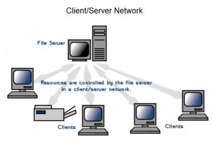
The entire control system for the Anti-surge controller will include the components similar to a PLC / ESD system (e.g. CPU/processor, Power supply modules, I/O cards, etc).
Author: Jatin Katrodiya
Read Next:


Sir
Your notes are very useful thank you for that.
I am confused about difference between instrument cable shield and screen.Can u just help me on that……
Instrument cable shield and cable screen are the same.
Sir this is very informative…
Coould you please explain about the bypass valve which is used in between suction and discharge of compressor.
Sir please provide details of hydraulic sov and possibly to control the valve with hydraulic sov with hydraulic actuator
Hello Aslam, Noted Down. Soon it will be posted. Thanks
Sir please send me a answer how to find ma for a minus to plus range ..e.g. -10 to 10 bar pressure..
Hi, Please check Formula Category. Click Here
Hello Sir,
A big fan of your site. I have question though, does different types of flow measurements (venturi, vortex, RO etc) impact the performance of the antisurge control loop?
Thanks,
Ashraf
Hi, Yes, there will be little impact and but we do not need to worry about it.
Dear sir,
How to make PI tuning for Anti surge controller?
This is very important subject, we need a math formula
any one please can give me a right answer for my question.
what is the reason for surge pressure ?
The author should have someone edit the text before publishing. It is obvious that the author knows his subject, but better use of proper English would give him more credibility. This comment is not meant to be negative, but constructive.
How effective on Anti Surge Controller tuning of 3 stage Centrifugal Air Compressor in AB SLC500/04 PLC as the control System in our case the Inlet Pressure Controller and a Blow Off VALVE.
Your effort to cover all aspects of the Anti-Surge control system is appreciated. I executed this work in the PDO project but don’t know much like this article. Thanks for sharing this article that is very informative for me.
Thank you. I learned things.
Hello.
One humble request is that can you please provide more information on the fallback strategy? (E.g. why it is needed, how it handle process input failures, how it operates in conjunction with typical Performance controller and surge controller)