The preventive maintenance (PM) of Instrument Air Compressor in Oil & Gas Plants are listed below.
- Check and record instrument air pressure.
- Inspect for tubing/fitting leakage.
- Check and blow down the condensate traps.
- Drain the condensate from the inlet airline drip leg. Do not open the valve with the compressor operating.
- Drain the condensate from the discharge header drip leg.
- Drain the condensate from the bypass airline drip leg.
- Drain the drip legs on any other horizontal run of air piping.
- Check for oil leaks. Correct as necessary.
- Inspect for gasket/O-ring leakage.
- Check for water leaks. Correct as necessary.
- Open the control air line drip leg valve to remove any moisture that may have collected.
- Check the instrument air line filter. Drain any moisture, which may have collected.
Quarterly Maintenance
- Inspect instrument air filter.
- Drain and clean the filter.
- Replace the element.
- Drain control air drip leg.
- Inspect condensate traps.
- Remove and clean. Replace parts as necessary.
- Replace trap if necessary.
- Inspect control panel.
- Watch for: loose wiring, wrong line filter, damaged line filter, and adequate arc suppressors.
- Clean panel fan filters and panel.
- Disconnect and tie back all unused wires from terminal strips.
- Check the vibration transmitter wires to make sure they run directly to the microcontroller terminal strips.
Semi-Annual Maintenance
- Follow the quarterly schedule.
- Check the control system per the procedure found in the Control section of the Operation Manual.
- Check the inlet and bypass valve calibration.
Annual Maintenance
- Execute the same checks as during Semi-Annual maintenance.
- Visually inspect the inlet throttle valve.
- Visually inspect the bypass valve.
Maintenance Procedures
Control Panel
The control panel checkout procedure is designed to verify that a control panel is functioning properly. The checkout can be used for initial testing or in conjunction with routine maintenance schedules.
Refer to the control drawings and checkout procedure included with the Control Panel Instructions in this manual to ensure proper adjustments and calibrations.
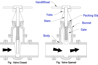
Inlet Valve
Filters require periodic cleaning and replacement. A daily draining of the regulator coalescing filter will indicate the severity of any contamination problem.
Periodically stroke the inlet valve to aid in optimum performance of the compressor preferably every six months.
Observe for freedom of movement of the inlet valve during the stroking procedure.
Bypass Valve
Periodically stroke the bypass valve to aid in optimum performance of the compressor.
In addition to stroking, the bypass valve should be removed from the air piping system annually to inspect the seals for damage.
Replace damaged seals as required and reinstall the valve.
Stroking of Inlet & Bypass Valve
1. With 4mA supplied to the positioner. Rotate ZERO adjustment nut wheel until:
- The INLET valve is fully closed.
- BYPASS valve is fully open.
2. Increase to 20mA and adjust the SPAN adjustment on the positioner terminal board until.
- INLET valve moves to fully open.
- BYPASS valve moves to fully closed.
3. Decrease source to 4mA and check the zero adjustment position of the valve.
4. Repeat zero and span procedure until valves are fully open and closed at their respective mA values.
Verifying proper operation of the Inlet & Bypass Valve Assembly:
Verify air supply:
Remove the regulator adjustment screw cap and back off on the adjustment screw until pressure indicated on the outlet pressure gauge is Zero.
Increase pressure to the operating pressure of 60 PSIG (414 kPa).
Verify positioner cam position:
INLET valve: Cam should be on side B with the arrow of the 0-100% range pointing to the left as the cam is viewed.
BYPASS valve: Cam should be on side A with the arrow of the 0-100% range pointing to the right as the cam is viewed.
Note: The above points may change depends on compressor vendors and models.
Attach a 4-20 mA source (+ to + and – to -) to the positioner.
Adjust the source so that 4 Ma is being sent to the positioner and observe valve action.
INLET and BYPASS valve action: Should not have moved as a result of applying the 4 mA.
Adjust source to 20 mA. Note valve action.
INLET valve action: Should open 90-degree. The positioner indicator should show a 90-degree rotation.
BYPASS valve action: Should close 90-degree. The positioner indicator should show a 90-degree rotation.
If valve action occurs as noted, the valves are properly stroked and ready to receive control signals from the MP3 microcontroller.
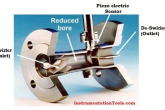
Checking Vibration
Periodically monitor shaft vibration on both sides of the coupling with a vibration analyzer.
In normal operation do not run the unit when vibration levels, as measured on the shaft, exceed two (2) mils on three thousand to thirty-six hundred (3000-3600) RPM drivers and two and one half (2-1/2) mils on fifteen to eighteen hundred (1500-1800) RPM drivers.
If vibration is measured using a non-contacting probe, add one half (1/2) mil to the above levels. If vibration levels exceed the above values shut the unit down and determine the cause of vibration.
Note: The vibration parameter values or any other above mentioned values may change as per the vendor or model of the IA compressor. These are only for reference.
Interest to add any further points? Share with us through below comments section.
Read Next:
- Air compressor Philosophy
- Anti-surge Controller
- Split Range Control Loop
- PID Controller Response
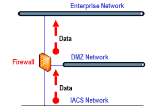
- Industrial Communication


The control panel checkout procedure is designed to verify that a control panel is functioning properly. The checkout can be used for initial testing or in conjunction with routine maintenance schedules.
Thanks for the post information.