Inst ToolsInst ToolsInst Tools
  • Ask
  • Courses
  • Videos
  • Q & A
    • Interview
      • Instrumentation
      • Electronics
      • Electrical
      • Practical Questions
    • MCQ
      • Instrumentation MCQ
      • Electrical MCQ
      • Electronics MCQ
      • Control Systems MCQ
      • Analog Electronics MCQ
      • Digital Electronics MCQ
      • Power Electronics MCQ
      • Microprocessor MCQ
      • Multiple Choice Questions
  • EE
    • Electronics
      • Electronics Q & A
      • Electronic Basics
      • Electronic Devices & Circuits
      • Electronics Animation
      • Digital Electronics
    • Electrical
      • Electrical Basics
      • Electrical Q & A
      • Power Electronics
      • Electrical Machines
      • Electrical Animation
      • Power Systems
      • Switchgear & Protection
      • Transmission & Distribution
  • Measure
    • Control Valves
    • Calibration
    • Temperature
    • Pressure
    • Flow
    • Level
    • Analyzers
    • Switches
    • Vibration
    • Solenoid Valve
  • Control
    • PLC Tutorials
    • Control Systems
    • Safety Instrumented System (SIS)
    • Communication
    • Fire & Gas System
  • More
    • Design
    • Tools
    • Animation
    • Basics
    • Formulas
    • Standards
    • TextBooks
    • Common
    • Software
    • Excel Tools
    • Erection & Commissioning
    • Process Fundamentals
    • Videos
    • Books
Search
All rights reserved. Reproduction in whole or in part without written permission is prohibited.
Reading: Alarm Simulator for Annunciator Logic
Share
Notification Show More
Font ResizerAa
Inst ToolsInst Tools
Font ResizerAa
  • Courses
  • PLC Tutorials
  • Control Systems
Search
  • Ask
  • Courses
  • Videos
  • Q & A
    • Interview
    • MCQ
  • EE
    • Electronics
    • Electrical
  • Measure
    • Control Valves
    • Calibration
    • Temperature
    • Pressure
    • Flow
    • Level
    • Analyzers
    • Switches
    • Vibration
    • Solenoid Valve
  • Control
    • PLC Tutorials
    • Control Systems
    • Safety Instrumented System (SIS)
    • Communication
    • Fire & Gas System
  • More
    • Design
    • Tools
    • Animation
    • Basics
    • Formulas
    • Standards
    • TextBooks
    • Common
    • Software
    • Excel Tools
    • Erection & Commissioning
    • Process Fundamentals
    • Videos
    • Books
Follow US
All rights reserved. Reproduction in whole or in part without written permission is prohibited.
Inst Tools > Blog > Control Systems > Alarm Simulator for Annunciator Logic

Alarm Simulator for Annunciator Logic

Last updated: September 22, 2021 7:28 pm
Editorial Staff
Control Systems Excel Tools
8 Comments
Share
2 Min Read
SHARE

This Alarm Simulator Excel Spreadsheet helps you to simulate an alarm and useful for learning its basic logic.

annunciator-alarm-simulator

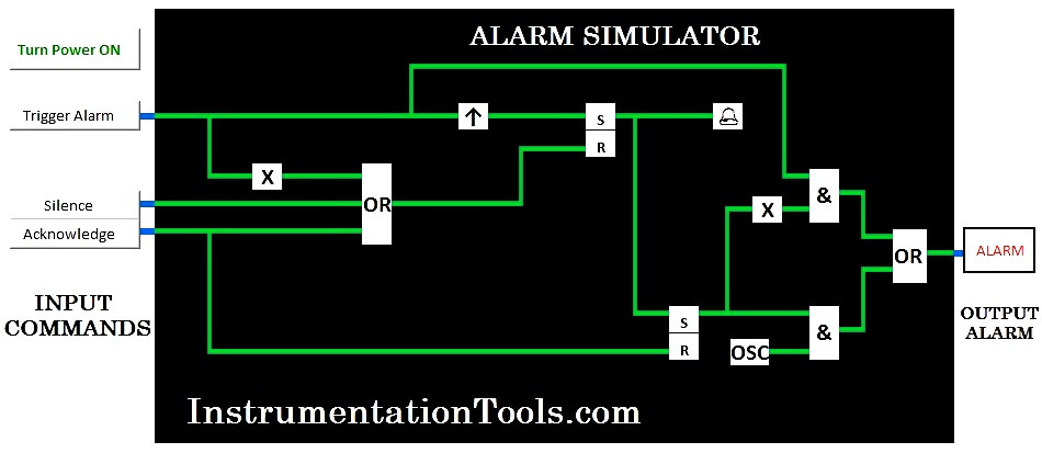
This excel simulates alarm logic used in alarming systems such as fire alarms, intruder alarms and process alarms in a process plant. The circuit is a combination of logic gates, SR flip flops and an oscillator.

The components labelled ‘X’ are NOT gates and the device marked with an UP arrow is a positive edge trigger.

DOWNLOAD ALARM SIMULATOR -1

DOWNLOAD ALARM SIMULATOR -2

Password : instrumentationtools.com

Note: Enable Excel Macros in order to work the simulator properly.

The alarm logic is as follows:

1. The circuit is started when powered up by pressing the ‘Turn Power On’ button.

2. An alarm event, created by pressing the ‘Trigger Alarm’ button generates an audio alarm and a flashing visual alarm. Examples of alarm events in real life could be detection of smoke or increasing in the temperature of a reactor.

3. The audio alarm is silenced by either pressing the ‘Silence’ or ‘Acknowledge’ buttons or when the alarm condition is cleared by pressing the ‘Clear Alarm’ button.

4. The visual alarm keeps flashing till acknowledged by pressing the ‘Acknowledge’ button. If the alarm condition remains, the visual alarm remains on when acknowledged. It clears when the alarm is acknowledged and cleared.

5. The circuit is powered off when the ‘Turn Power Off’ button is pressed.

The circuit is animated, and the various connections show the energized (logic state 1) and de-energized (logic state 0) states. Electrical convention is followed, green colour indicates the de-energized state and red indicates the energized state.

Also Read : What is a Inductive Proximity Switch ?

Don't Miss Our Updates
Be the first to get exclusive content straight to your email.
We promise not to spam you. You can unsubscribe at any time.
Invalid email address
You've successfully subscribed !
Difference between DCS & PLC Systems
PID Simulator Download
Selection of Components Used In Electrical Earthing or Grounding
4-wire Passive versus Active Transmitters
Learn about SCADA and HMI Systems
Share This Article
Facebook Whatsapp Whatsapp LinkedIn Copy Link
Share
8 Comments
  • Senthil says:
    June 25, 2015 at 8:42 am

    Simulator was working excellent. Thanks for sharing.

    Reply
  • shazly says:
    November 22, 2015 at 2:33 pm

    please what is the password for alarm simulation sheet

    Reply
    • S Bharadwaj Reddy says:
      November 22, 2015 at 3:30 pm

      hi, Password: instrumentationtools.com

      Reply
  • Shridhar says:
    February 26, 2016 at 9:00 am

    S Bharadwaj Reddy can I get your personal mail ID or contact number.

    Reply
    • S Bharadwaj Reddy says:
      February 26, 2016 at 9:19 am

      Mail me at instrumentationTools@gmail.com

      Reply
  • mohd says:
    March 13, 2016 at 8:07 pm

    sir may i know y it is not installing in my 64 bit laptop do we need any other configracation

    Reply
    • S Bharadwaj Reddy says:
      March 14, 2016 at 3:43 am

      Hello, It is a Excel file only. So Please check your Ms-office software. Thanks

      Reply
  • arif says:
    November 21, 2022 at 8:04 pm

    kindly send password of simulator rar files

    Reply

Leave a Reply Cancel reply

Your email address will not be published. Required fields are marked *

Stay Connected

128.3kFollowersLike
69.1kFollowersFollow
208kSubscribersSubscribe
38kFollowersFollow

Categories

Recent Comments

  • Guifty Shimica on Top Non-PLC Certification Courses for Automation Professionals
  • Guifty Shimica on Top Non-PLC Certification Courses for Automation Professionals
  • MIHARITSOA Aina Sitraka on Top Non-PLC Certification Courses for Automation Professionals
  • Vaishnavi on Free Instrumentation Course for Trainee Engineers

Related Articles

What is a Network Switch?

Network Switch Requirement in SCADA and DCS Architecture

IACS Network

Remote Connectivity to Industrial Automation Systems

Safety Control System

What is Safety Control System ?

ICS System Design

ICS System Design Considerations

Distributed Control Systems (DCS)

What is DCS? (Distributed Control System)

Cable Glands

Using of MCT instead of Cable Glands on the Cabinets

SCADA RTU TELEMETRY

SCADA & Telemetry Systems

Troubleshooting PLC Current Loops

Troubleshooting Current Loops with Voltage Measurement

More Articles

U-tube Manometer unEqual Limb Type

U-tube Manometer with equal & unequal limb types

Ammonia Analyzer Working

Ammonia Analyzer Principle

High-Speed and Fast Counters in PLC

What are High-Speed Counters and Fast Counters in PLC?

What can you do with an Engineering Degree

What Can You Do with an Engineering Degree?

3-15 psi to 4-20mA Conversion

Example of 3-15 psi to 4-20mA Conversion

Erratic H2 Flow Rotameter

Erratic H2 Flow Rotameter

Transducers MCQ

Transducers MCQ

Pressure Gauge Calibration according to Standard DKD-R-6-1

Pressure Gauge Calibration according to Standard DKD-R-6-1

Follow US
All rights reserved. Reproduction in whole or in part without written permission is prohibited.
Welcome Back!

Sign in to your account

Username or Email Address
Password

Lost your password?