Feedforward control works by directly modulating the manipulated variable in a control system according to changes sensed in the load(s).
In order for feedforward to function optimally, it must adjust the manipulated variable in a manner that is proportionate to the need: no more, and no less.
At this juncture it is appropriate to ask the question, “how do we know the amount of feedforward action that will be adequate for a process, and how do we adjust it if it is too much or too little?”
In processes where the feedforward control strategy attempts to achieve direct mass- or energy balance, the question of adequate feedforward action is answered in the mathematics of measuring the incoming and outgoing flows.
Consider the following mass-balance level control system where the combined sum of three inlet flows is routed to the setpoint of the exit flow control loop.
In this diagram, the portions of the control strategy implemented as function blocks (algorithms in software) appear inside a yellow-colored bounded area, while all real physical instruments appear outside the yellow area:
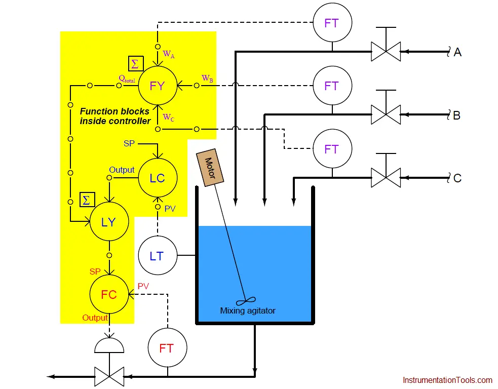
If all flowmeters are calibrated in pounds per minute, then the feedforward signal will likewise be scaled in pounds per minute, and so will the setpoint be for flow control loop.
In a digital control system, it is quite customary to scale each and every analog input signal with some real “engineering unit” of measurement, so that the signal will be treated as a physical quantity throughout as opposed to being treated as some anonymous percentage value.
Not only is this consistent scaling a standard feature in digital control systems, but it also helps the implementation of this feedforward control strategy, because we desire the out-going mass flow rate to precisely match the (total) in-coming flow rate.
So long as all flowmeters and their associated scaling factors are accurate, the feedforward control’s action must be exactly right: an increase of +5 pounds per minute in incoming flow rate will prompt an immediate increase of +5 pounds per minute in outgoing flow rate, simply by virtue of all these measured flows having been scaled in the same unit of measurement.
The situation is not as simple in systems where the feedforward control is not precisely balancing mass-flow or energy rates. By contrast, let us examine the following pH neutralization system equipped with feedforward control action.
Here, the incoming liquid is alkaline (pH greater than 7), and the control system’s job is to mix just enough acid reagent to “neutralize” the solution (bring the pH value down to 7):
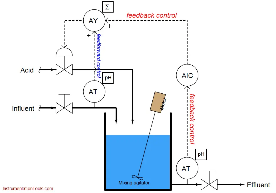
Controlling the pH ( acidity/alkalinity) of a liquid solution is challenging for many reasons, not the least of which being the need to have adequate mixing time for the reagent to react with the influent.
This mixing time translates to dead time in the feedback control system. If the influent’s pH suddenly changes for any reason, the feedback control system will be slow to alter the reagent flow rate due to this dead time, causing long-lasting deviations from setpoint.
The goal of the feedforward signal (from the influent pH transmitter to the summer) is to preemptively adjust reagent flow rate according to how alkaline the incoming flow is, countering any sudden changes in influent pH so the feedback control system doesn’t have to take (delayed) action.
Once again, it is appropriate to ask the question, “how do we know the amount of feedforward action that will be adequate for this process, and how do we adjust it if it is too much or too little?” It would be blind luck if the system happened to work perfectly as shown, with the influent pH transmitter’s signal going straight to the summing function to be added to the pH controller’s output signal.
Certainly, an increase in influent pH would cause more acid to be added to the mix thanks to feedforward action, but it would likely add either too much or too little acid than it should. The scale of the influent pH transmitter does not match the scale of the signal sent to the control valve, and so we do not have a neat “pound-for-pound” balance of mass flow as we did in the case of the level control system.
A neat solution to this problem is to add another function block to the feedforward portion of the control system. This block takes the influent pH transmitter signal and skews it using multiplication and addition, using the familiar linear equation y = mx + b (where y is the output signal of the function and x is the input signal; m and b being constants).
This function block is typically called a gain and bias block:
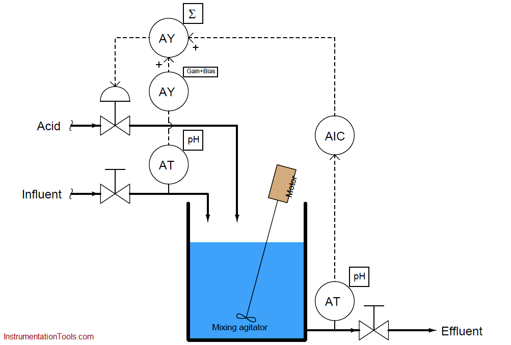
The gain adjustment (m) in this function block serves to amplify or attenuate the feedforward signal’s magnitude, while the bias adjustment (b) offsets it.
Determining practical values for these “feedforward tuning constants” is relatively easy. First, disable feedback control (Note 1 ) with the output value at or near 50%.
Next, introduce load changes to the process while watching the process variable’s value after sufficient time has elapsed to see the effects of those load changes. Increase or decrease the gain value until step-changes in load cease to yield significant changes in the process variable.
Note 1 : Most control systems’ feedforward function blocks are designed in such a way that both the feedback and the feedforward signal paths are disabled when the controller is placed into manual mode, in order to give the human operator 100% control over the final element (valve) in that mode.
For the purpose of “tuning” the feedforward gain/bias function block, one must disable the feedback control only so feedforward action is still able to respond to load changes. If simply switching the feedback controller to manual mode is not an option (which it usually is not), one may achieve the equivalent result by setting the gain value of the feedback controller to zero and ensuring the PID equation is not the “parallel” type. If the PID equation is parallel, you will need to set all three terms (P, I, and D) at their minimum settings.
The following trends show what too much and too little feedforward gain would look like in this pH control system:
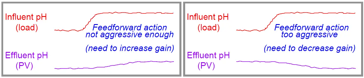
If the gain is properly set in the gain/bias function block, these load changes should have minimal effect on the process variable.
Step-changes in influent pH should have little effect on the process variable after sufficient time has passed for the load change to have fully propagated through the process. Once a good gain value has been found, change the bias value until the process variable approaches the normal setpoint value (note 2 ).
Note 2 : This is why it was recommended to leave the feedback controller’s output at or near 50%. The goal is to have the feedforward action adjusted such that the feedback controller’s output is “neutral,” and has room to swing either direction if needed to provide necessary trim to the process.
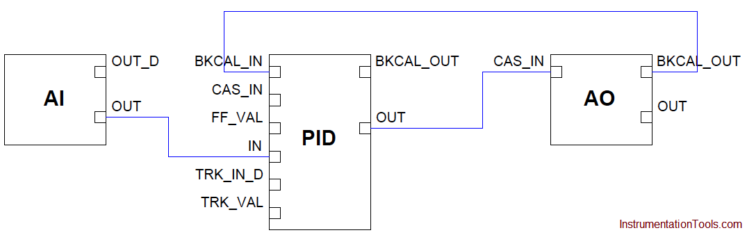
Some control systems provide convenient methods of incorporating feedforward action. The standard FOUNDATION Fieldbus PID function block, for example, has its own dedicated signal input for feedforward, with feedforward gain as an existing parameter.
The following illustration shows Fieldbus function blocks used to implement normal feedback (PID) control, and also PID with feedforward control:
Standard PID control algorithm with FF function blocks
PID with Feedforward
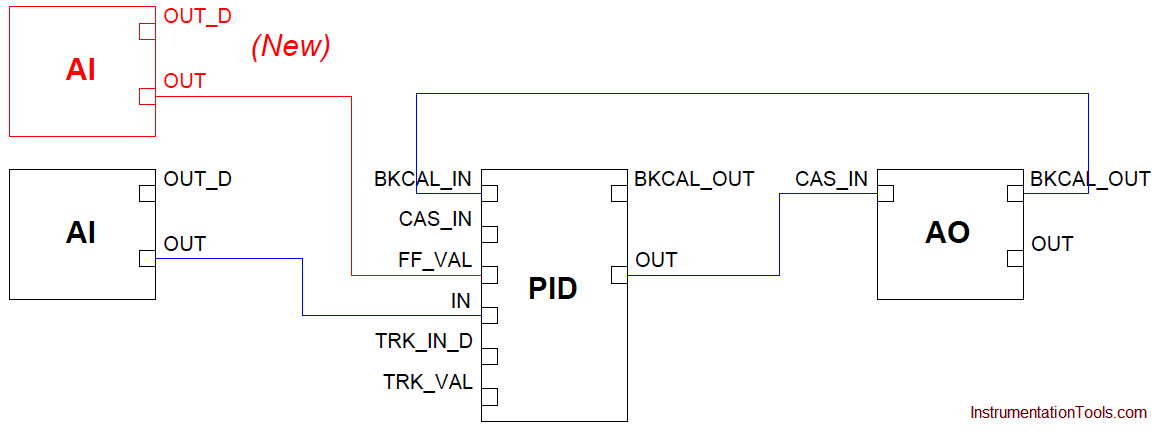
As you can see, all that is required to augment a FOUNDATION Fieldbus control system with feedforward control action is the addition of one more analog input (AI) function block for the load transmitter, and one connecting line between that block and the PID block’s “FF Val” input.
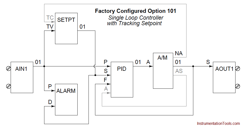
Other control systems require a bit more programming to implement feedforward. For example, consider the standard “Factory Configured Option 101” function block program for basic PID feedback control in a Siemens model 353 panel-mounted loop controller, contrasted against the version necessary for implementing feedforward action:
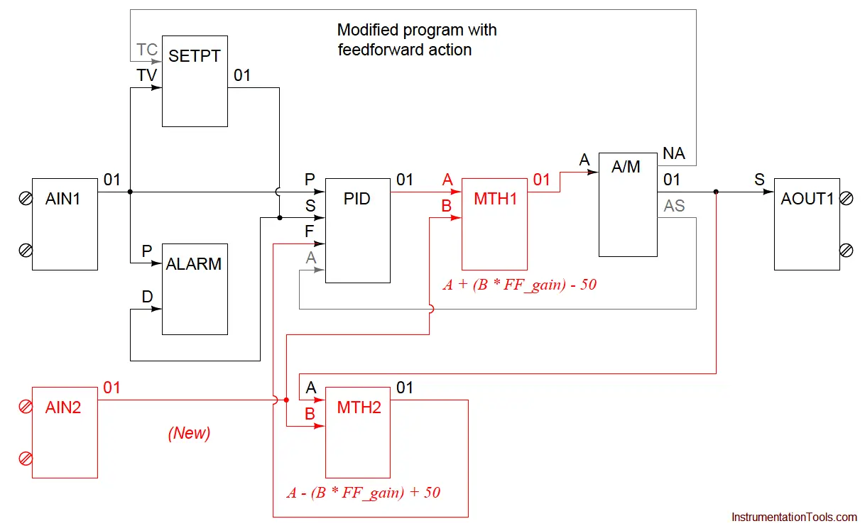
Note the necessary addition of two “math” function blocks as well as the extra analog input block for receiving the feedforward (load variable) transmitter’s signal: MTH1 needed to add the load transmitter’s feedforward signal to the controller’s output signal, and MTH2 needed to ensure output tracking still works properly between the PID and A/M function blocks when the human operator switches between automatic and manual modes.
The amount of feedforward action is specified by the “gain” parameter for input B of both math function blocks, which means any adjustment to feedforward action must be manually entered in two different places!