Inst ToolsInst ToolsInst Tools
  • Courses
  • Automation
    • PLC
    • Control System
    • Safety System
    • Communication
    • Fire & Gas System
  • Instrumentation
    • Design
    • Pressure
    • Temperature
    • Flow
    • Level
    • Vibration
    • Analyzer
    • Control Valve
    • Switch
    • Calibration
    • Erection & Commissioning
  • Interview
    • Instrumentation
    • Electrical
    • Electronics
    • Practical
  • Q&A
    • Instrumentation
    • Control System
    • Electrical
    • Electronics
    • Analog Electronics
    • Digital Electronics
    • Power Electronics
    • Microprocessor
  • Request
Search
  • Books
  • Software
  • Projects
  • Process
  • Tools
  • Basics
  • Formula
  • Power Plant
  • Root Cause Analysis
  • Electrical Basics
  • Animation
  • Standards
  • 4-20 mA Course
  • Siemens PLC Course
Reading: Allen Bradley Bitwise Logical Operations
Share
Font ResizerAa
Inst ToolsInst Tools
Font ResizerAa
  • Courses
  • Design
  • PLC
  • Interview
  • Control System
Search
  • Courses
  • Automation
    • PLC
    • Control System
    • Safety System
    • Communication
    • Fire & Gas System
  • Instrumentation
    • Design
    • Pressure
    • Temperature
    • Flow
    • Level
    • Vibration
    • Analyzer
    • Control Valve
    • Switch
    • Calibration
    • Erection & Commissioning
  • Interview
    • Instrumentation
    • Electrical
    • Electronics
    • Practical
  • Q&A
    • Instrumentation
    • Control System
    • Electrical
    • Electronics
    • Analog Electronics
    • Digital Electronics
    • Power Electronics
    • Microprocessor
  • Request
Follow US
All rights reserved. Reproduction in whole or in part without written permission is prohibited.
Inst Tools > Blog > PLC Tutorials > Allen Bradley Bitwise Logical Operations

Allen Bradley Bitwise Logical Operations

Last updated: March 4, 2021 3:22 pm
Editorial Staff
PLC Tutorials
No Comments
Share
5 Min Read
SHARE

To study the working of Allen Bradley Bitwise logical operations like AND, OR, NOT, XOR in Programmable logic Controllers (PLC).

Contents
Bitwise Logical OperationsBlock Name: Bitwise ANDBlock Name: Bitwise ORBlock Name: Bitwise XORBlock Name: Bitwise NOTPLC LADDER EXAMPLECASE 1:BITWISE Operation of AND, OR, XOR, NOT:AND Logic:OR Logic :XOR Logic :NOT Logic :CASE 2:BITWISE Operation of AND, OR, XOR, NOT:AND logic:OR Logic:XOR Logic:NOT Logic:Conclusion:

Bitwise Logical Operations

Block Name: Bitwise AND

Bitwise AND Instruction

In the above picture, there are totally three parameters,

SOURCE A – Address of First Binary Value

SOURCE B – Address of Second Binary Value

DESTINATION –AND operation result of Source A & B stored in this address

Block Name: Bitwise OR

Bitwise OR Instruction

In the above picture, there are totally three parameters,

SOURCE A –Address of First Binary Value

SOURCE B –Address of Second Binary Value

DESTINATION –OR operation result of Source A & B stored in this address

Block Name: Bitwise XOR

Bitwise XOR Instruction

In the above picture, there are totally three parameters,

SOURCE A –Address of First Binary Value

SOURCE B –Address of Second Binary Value

DESTINATION –XOR operation result of Source A & B stored in this address

Block Name: Bitwise NOT

Bitwise NOT Instruction

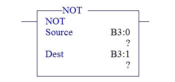
In the above picture, there are totally two  parameters,

SOURCE -Address of Binary Value

DESTINATION –NOT operation result of Source stored in this address

PLC LADDER EXAMPLE

Working of Bitwise logical operation in AB PLC

CASE 1:

When,

Source A : 0000 0000 0000 0000 (AND,OR & XOR)

Source B : 0000 0000 0000 0000 (AND,OR & XOR)

Source  : 0000 0000 0000 0000 (NOT)

Rung 0000:

All Bitwise operator block are connected in parallel with input condition I: 0/0. When it goes ON, each block performs its operation. Since Source addresses are having zeros except NOT block remaining blocks are resulting 0s.

BITWISE Operation of AND, OR, XOR, NOT:

AND Logic:

Source A : 0000 0000 0000 0000   (B3:0)

Source B : 0000 0000 0000 0000   (B3:1)

Destination : 0000 0000 0000 0000   (B3:2)

OR Logic :

Source A : 0000 0000 0000 0000   (B3:0)

Source B : 0000 0000 0000 0000   (B3:1)

Destination : 0000 0000 0000 0000   (B3:3)

XOR Logic :

Source A : 0000 0000 0000 0000   (B3:0)

Source B : 0000 0000 0000 0000   (B3:1)

Destination : 0000 0000 0000 0000   (B3:4)

NOT Logic :

Source: 0000 0000 0000 0000   (B3:0)

Destination : 1111 1111 1111 1111  (B3:5)

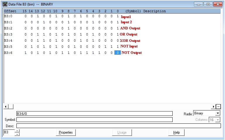
DATA FILE FOR CASE 1:

Bitwise Instructions

CASE 2:

When,

Source A : 0010  0101 0100 0001   (AND,OR & XOR)

Source B : 0001 0001 0001  0001  (AND,OR & XOR)

Source  :0101 0100 1000 0111 (NOT)

PLC Program using Bitwise Instructions

Rung 0000:

I:0/0 giving input condition to all Bitwise Blocks. When it goes ON, value placed in Source A and Source B performs respective operation depends on blocks.

BITWISE Operation of AND, OR, XOR, NOT:

AND logic:

Source A : 0010  0101 0100 0001   (B3:0)

Source B : 0001 0001 0001  0001  (B3:1)

Destination : 0000 0001 0000 0001  (B3:2)

OR Logic:

Source A : 0010  0101 0100 0001   (B3:0)

Source B : 0001 0001 0001  0001  (B3:1)

Destination : 0011 0101 0101 0001  (B3:3)

XOR Logic:

Source A : 0010  0101 0100 0001   (B3:0)

Source B : 0001 0001 0001  0001  (B3:1)

Destination : 0011 0100 0101 0000  (B3:4)

NOT Logic:

Source: 0101 0100 1000 0111 (B3:0)

Destination : 1010 1011 0111 1000  (B3:5)

DATA FILE FOR CASE 2:

Data File for Bitwise Logics

Conclusion:

We can use this explanation to understand the working of Bitwise logical operation like AND, OR, NOT, XOR in Allen Bradley Programmable logic Controllers (PLC).

Author : Hema Sundaresan

If you liked this article, then please subscribe to our YouTube Channel for PLC and SCADA video tutorials.

You can also follow us on Facebook and Twitter to receive daily updates.

Read Next:

How to use Converters in PLC

Ladder Logic using Toggle Switch

Basics of Interlocking in PLC

PLC Configuration Systems

Boolean Algebra using PLC

Don't Miss Our Updates
Be the first to get exclusive content straight to your email.
We promise not to spam you. You can unsubscribe at any time.
Invalid email address
You've successfully subscribed !

Continue Reading

How to Use ModScan Software for Testing Modbus Communication?
PLC Light Sequence Control using Bit Shift Registers
Single-acting Pneumatic Cylinder Operation with Limit Switch
Control Algorithms in PLC Programming
What is Loop Checking?
How to Download GX Works? Mitsubishi PLC Software
Share This Article
Facebook Whatsapp Whatsapp LinkedIn Copy Link
Share
Leave a Comment

Leave a Reply Cancel reply

Your email address will not be published. Required fields are marked *

Stay Connected

128.3kFollowersLike
69.1kFollowersFollow
210kSubscribersSubscribe
38kFollowersFollow

Categories

Explore More

Basics of Sinking and Sourcing – Automation System MCQ
Comparator in PLC Programming
PLC Program for Blinking Lamp on 5 Seconds Interval
Yokogawa DCS and SIS System Architecture
PLC Sequence Programming Ladder Logic
Basics of PLC Programming
PLC System Site Acceptance Test (SAT)
DC Injection Braking in VFD

Keep Learning

PLC Circuit with Switches

PLC Example with Switches

RSLogix 5000 PLC Programming Procedure

PLC analog input scaling

PLC Analog Input Scaling

Configure Analog Inputs and Outputs in Delta PLC

How to Configure Analog Inputs and Outputs in Delta PLC?

A Typical Sequential Function Chart

What is Sequential Function Chart (SFC?)

PLC Important Questions and Answers

PLC Important Questions and Answers

PLC program for VFD Drive Multiple Speeds

Drive Multiple Speeds with Different Reference using PLC

Programmable Logic Controller Boiler Logic

PLC Ladder Logic for Start-up Control of Boilers

Learn More

PLC Scan Time

PLC Scan Time

Identify Instrumentation Terms in Water Supply System

Identify Instrumentation Terms in Water Supply System

Solenoid Valve Terminology

Solenoid Valve Terminology Questions and Answers

Difference between MCB and RCBO

Difference Between MCB and RCBO

electromechanical-level-measurement-working-principle

ElectroMechanical Level Measurement Working Principle

Gas Detectors Bump Testing

What is Bump Testing ?

RTD Standards list

RTD Standards

PLC FBD Programming for Burglar Alarm Security System

PLC FBD Programming for Burglar Alarm Security System

Menu

  • About
  • Privacy Policy
  • Copyright

Quick Links

  • Learn PLC
  • Helping Hand
  • Part Time Job

YouTube Subscribe

Follow US
All rights reserved. Reproduction in whole or in part without written permission is prohibited.
Welcome Back!

Sign in to your account

Username or Email Address
Password

Lost your password?