Advanced PLC programming for defective parts sorting to distinguish between good and bad parts and then transport them via conveyors.
Advanced PLC Programming for Defective Parts Sorting
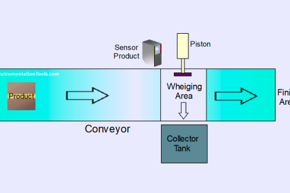
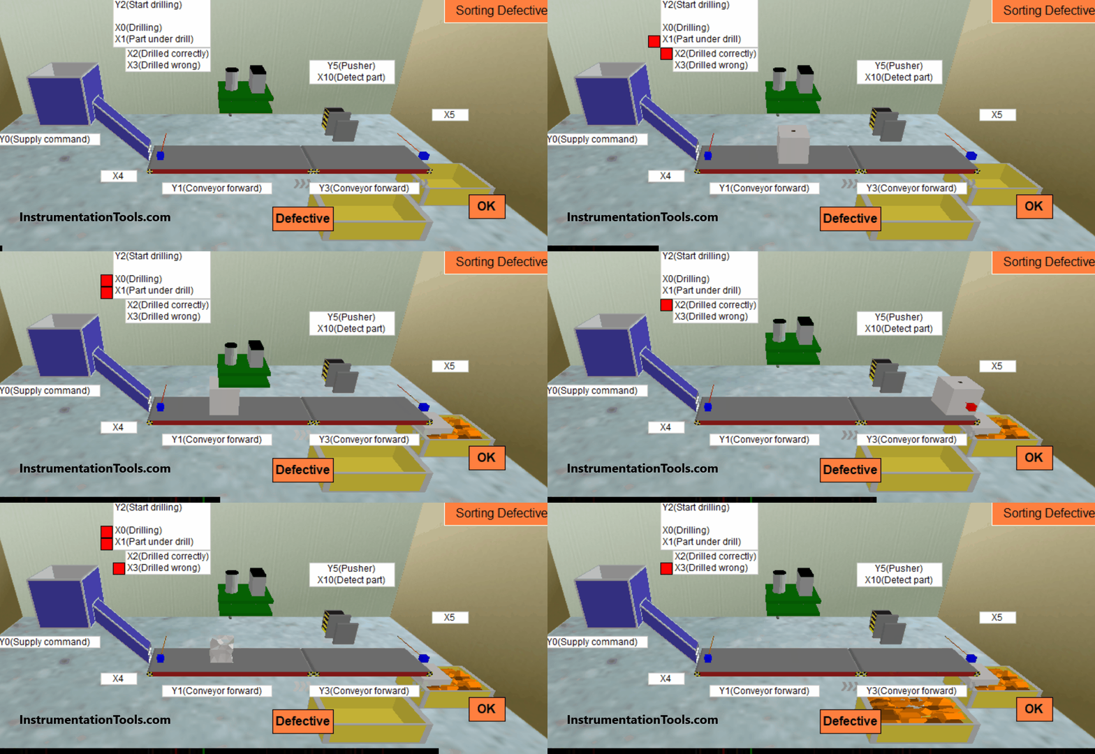
The below simulation shows the good and bad products identification and sorting the products based on their quality using PLC ladder logic.
The conveyors are used to move the products. The conveyors are started and stopped when the products are delivered on the conveyor and during the drilling operation.
The drill machine is used for drilling the products as per the design. Sometimes the drilling operation may damage the products.
A sensor detects the quality of the products and a pusher is used to push the bad products into another storage bin.
PLC Inputs and Outputs
The below table lists the required inputs and outputs of the PLC system.
| Type | Device No. | Device name | Operation |
| Input | X0 | Drilling | ON while drilling. |
| Input | X1 | Part under drill | One part is supplied when Y0 is ON: A large metal cube. |
| Input | X2 | Drilled correctly | ON when the part is drilled correctly. The previous result is cleared when drilling starts. |
| Input | X3 | Drilled wrong | ON when the part is detected at the left end. |
| Input | X4 | Sensor | ON when the part is detected at the right end. |
| Input | X5 | Sensor | ON when the part is detected in front of the pusher. |
| Input | X10 | Sensor | ON when the part is not drilled correctly. The previous result is cleared when drilling starts. |
| Output | Y0 | Supply command | The conveyor moves forward when Y1 is ON. |
| Output | Y1 | Conveyor forward | The conveyor moves forward when Y3 is ON. |
| Output | Y2 | Start drilling | Starts drilling when Y2 is ON (A process cycle that cannot be stopped partway). |
| Output | Y3 | Conveyor forward | Extends when Y5 is ON and retracts when Y5 is OFF. The pusher cannot be stopped in the mid-stroke. |
| Output | Y5 | Pusher | Extends when Y5 is ON and retracts when Y5 is OFF. The pusher cannot be stopped in the mid stroke. |
Program Description
This project aims to differentiate between good and defective parts using sensors and sorting them accordingly. The project consists of two key areas: overall control and drill control.
Overall Control
There is a pushbutton named PB1 (X20) on the control panel. When you press PB1, it triggers the Supply command (Y0) for the hopper, causing it to supply parts. Releasing PB1 deactivates the Supply command, stopping the hopper.
There is a switch, SW1 (X24), on the control panel. When you turn SW1 ON, the conveyors start to move forward. Turning SW1 OFF halts the conveyors.
Drill Control
Now let’s discuss the control of the drill:
When the Part under the drill sensor (X1) within the drill is activated, the conveyor halts.
The drilling process commences when the Start drilling command (Y2) is activated. It stops when the Drilling sensor (X0) is activated.
After one complete cycle of drill operation, if Start drilling (Y2) is activated, either the Drilled correctly (X2) or Drilled wrong (X3) sensor is triggered.
Note that the drill can’t be stopped mid-operation. In this PLC simulation, every third part is considered defective (A part with multiple holes also falls into the defective category).
When the Detect part sensor (X10) in the pusher identifies a defective part, the conveyor stops, and the pusher moves the part onto the ‘Defective’ tray.
Remember that when the actuating command for the pusher is ON, it fully extends. When the command is OFF, the pusher fully retracts.
A part that passes inspection continues along the conveyor to the ‘OK’ tray located at the right end.
PLC Programming
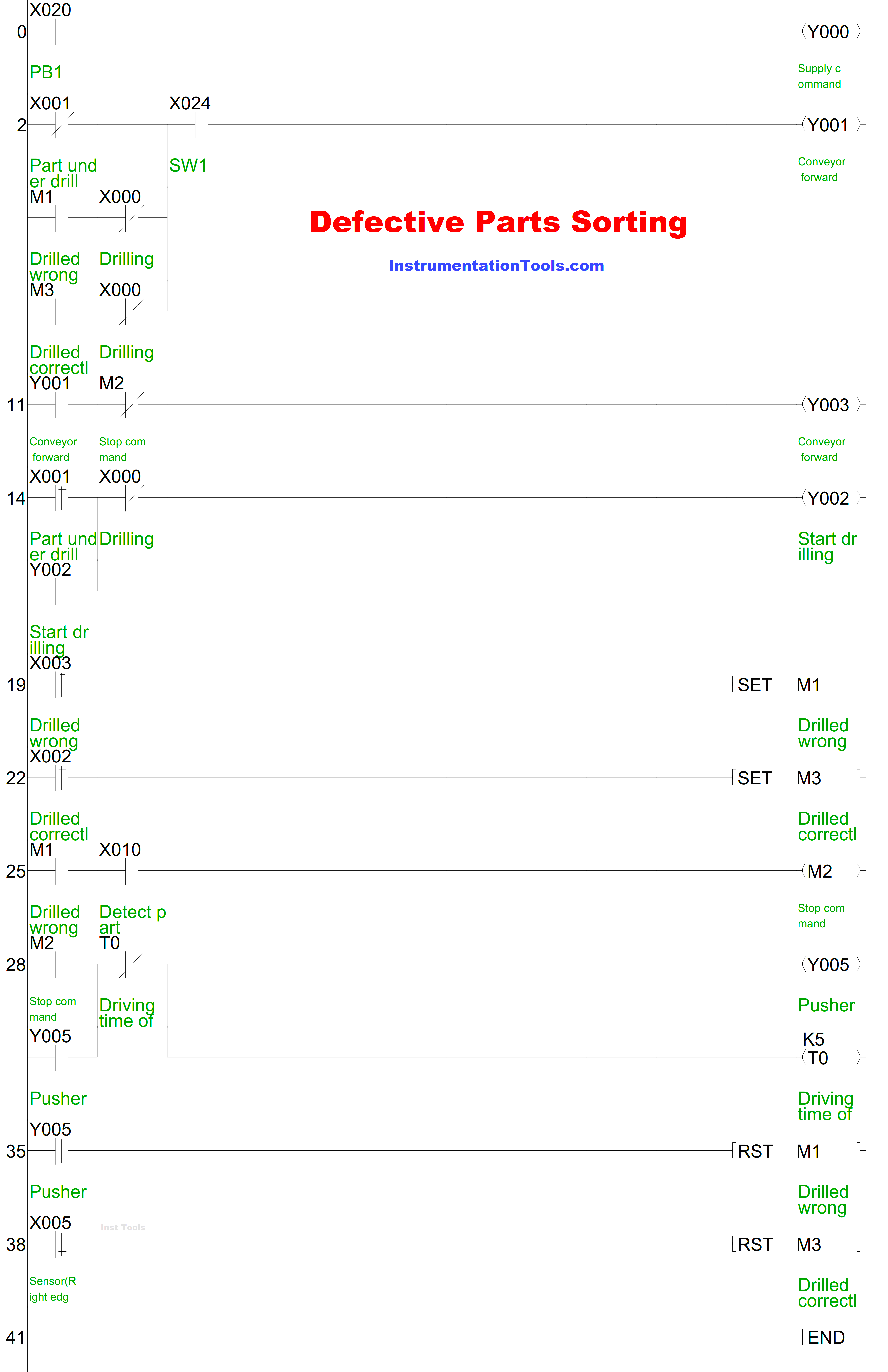
Source: Mitsubishi Electric
If you liked this article, then please subscribe to our YouTube Channel for Instrumentation, Electrical, PLC, and SCADA video tutorials.
You can also follow us on Facebook and Twitter to receive daily updates.
Read Next:
- Find the Best PLC for Your Project
- HMI Screens on a Mobile or Tablet
- Top Automation Vendors in World
- Tia Portal Interrupt Organization Block
- Types of Sensors Used in Automobiles
