Inst ToolsInst ToolsInst Tools
  • Ask
  • Courses
  • Videos
  • Q & A
    • Interview
      • Instrumentation
      • Electronics
      • Electrical
      • Practical Questions
    • MCQ
      • Instrumentation MCQ
      • Electrical MCQ
      • Electronics MCQ
      • Control Systems MCQ
      • Analog Electronics MCQ
      • Digital Electronics MCQ
      • Power Electronics MCQ
      • Microprocessor MCQ
      • Multiple Choice Questions
  • EE
    • Electronics
      • Electronics Q & A
      • Electronic Basics
      • Electronic Devices & Circuits
      • Electronics Animation
      • Digital Electronics
    • Electrical
      • Electrical Basics
      • Electrical Q & A
      • Power Electronics
      • Electrical Machines
      • Electrical Animation
      • Power Systems
      • Switchgear & Protection
      • Transmission & Distribution
  • Measure
    • Control Valves
    • Calibration
    • Temperature
    • Pressure
    • Flow
    • Level
    • Analyzers
    • Switches
    • Vibration
    • Solenoid Valve
  • Control
    • PLC Tutorials
    • Control Systems
    • Safety Instrumented System (SIS)
    • Communication
    • Fire & Gas System
  • More
    • Design
    • Tools
    • Animation
    • Basics
    • Formulas
    • Standards
    • TextBooks
    • Common
    • Software
    • Excel Tools
    • Erection & Commissioning
    • Process Fundamentals
    • Videos
    • Books
Search
All rights reserved. Reproduction in whole or in part without written permission is prohibited.
Reading: How Snubber Circuit works ?
Share
Notification Show More
Font ResizerAa
Inst ToolsInst Tools
Font ResizerAa
  • Courses
  • PLC Tutorials
  • Control Systems
Search
  • Ask
  • Courses
  • Videos
  • Q & A
    • Interview
    • MCQ
  • EE
    • Electronics
    • Electrical
  • Measure
    • Control Valves
    • Calibration
    • Temperature
    • Pressure
    • Flow
    • Level
    • Analyzers
    • Switches
    • Vibration
    • Solenoid Valve
  • Control
    • PLC Tutorials
    • Control Systems
    • Safety Instrumented System (SIS)
    • Communication
    • Fire & Gas System
  • More
    • Design
    • Tools
    • Animation
    • Basics
    • Formulas
    • Standards
    • TextBooks
    • Common
    • Software
    • Excel Tools
    • Erection & Commissioning
    • Process Fundamentals
    • Videos
    • Books
Follow US
All rights reserved. Reproduction in whole or in part without written permission is prohibited.
Inst Tools > Blog > Power Electronics > How Snubber Circuit works ?

How Snubber Circuit works ?

Last updated: June 3, 2017 5:23 am
Editorial Staff
Power Electronics
No Comments
Share
4 Min Read
SHARE

The Snubber circuit is one type of dv/dt protection circuit of the thyristor.

With the help of snubber circuit, the false turn-on of a thyristor due to large dv/dt can be prevented.

How Snubber Circuit works

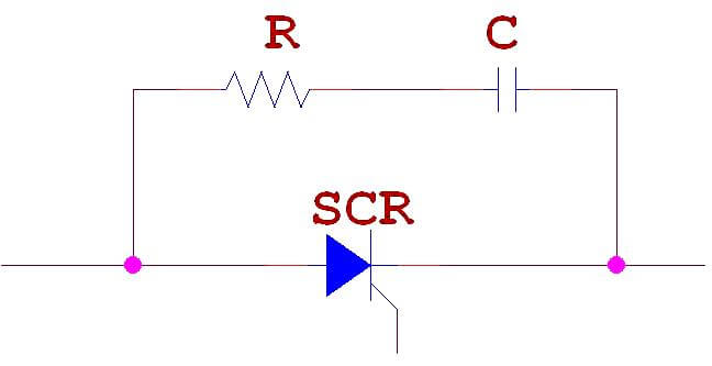
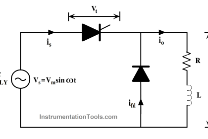
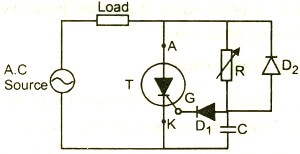
RC Snubber Circuit for SCR dv/dt Protection:

This type of snubber circuit consists of a series combination of resistance R and Capacitance C in parallel with a SCR.

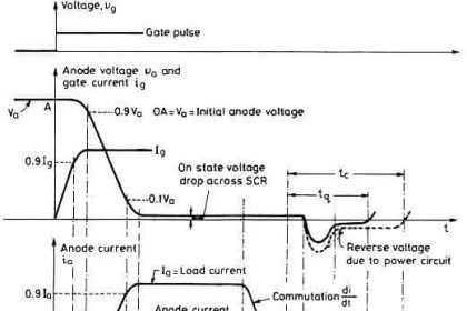
  • When a reverse voltage is applied, commutation process is initiated and the forward current flow through SCR approaches zero.
  • Due to the inductance, current continuous to flow due to sweeping of charge carries at the external junctions.
  • When it reaches a peak value it cannot be further supported by the charge carriers and falls very quickly to zero. This causes a voltage spike with the value of L(di/dt).
  • Also when the supply is closed to the circuit( in the above figure say the switch S is closed), sudden voltage appears across SCR.
  • Now, as the thyristor current is zero it can be considered as an open switch.
  • At this moment, the capacitor C behaves  like a short-circuit and therefore voltage across the SCR is zero.
  • With the passage of time capacitor C gets charged at a slow rate such that dv/dt across the capacitor and therefore across SCR is less than the specified maximum dv/dt rating of the device.
  • Thus the capacitor protects the SCR against high voltages and high dv/dt.

Based on the above discussion we can say that simply a Capacitor C is sufficient to protect the SCR against dv/dt false triggering.

Then what is the purpose of resistance R?

  • In the RC snubber circuit, the resistance R limits the discharge current of capacitor at the instant of firing of SCR.
  • Before SCR is fired, capacitor C charges to full voltage V.
  • If SCR is fired, when the capacitor voltage is maximum, it discharges through the local path formed by capacitor C, Resistance R and SCR.
  • During this time, if the resistance R is not included in the circuit, the discharge current will be high and consequently may damage the SCR due to large di/dt.
  • Thus the Resistance R in the snubber circuit reduces the discharge current of the capacitor C and thus protect the SCR against large di/dt.

In actual practice, R, C and the load current parameters should be such that

  1. dv/dt across C during its charging is less than the specified dv/dt rating of the SCR
  2. Discharge current at the turn ON of the SCR is within reasonable limits.

Normally R,S and load circuit parameters form an undamped circuit so that dv/dt is limited to acceptable values.

RC snubber circuits

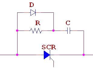
In some RC snubber circuits, a diode D used to connect in parallel with the resistor R. It is used for the purpose of bypass and thus giving improved dv/vt protection.

Don't Miss Our Updates
Be the first to get exclusive content straight to your email.
We promise not to spam you. You can unsubscribe at any time.
Invalid email address
You've successfully subscribed !
Phase-Controlled Half-Wave Rectifier With Freewheeling Diode
SCR Triggering Methods
R R-C Firing Circuits Disadvantages
Introduction to Thyristor – History, Types, Principle, Advantages
Thyristor Interview Questions & Answers
Share This Article
Facebook Whatsapp Whatsapp LinkedIn Copy Link
Share
Leave a Comment

Leave a Reply Cancel reply

Your email address will not be published. Required fields are marked *

Stay Connected

128.3kFollowersLike
69.1kFollowersFollow
208kSubscribersSubscribe
38kFollowersFollow

Categories

Recent Comments

  • Guifty Shimica on Top Non-PLC Certification Courses for Automation Professionals
  • Guifty Shimica on Top Non-PLC Certification Courses for Automation Professionals
  • MIHARITSOA Aina Sitraka on Top Non-PLC Certification Courses for Automation Professionals
  • Vaishnavi on Free Instrumentation Course for Trainee Engineers

Related Articles

Power Electronics Projects

Top 100 Power Electronics Projects for Engineering Students

Symbol of MOS Controlled Thyristor

MCT (MOS Controlled Thyristor) – Symbol, Working, Characteristics, Advantages

Types of Power Electronic Devices

Power Electronic Devices Specification and Classification

Full-Controlled Rectifier Working Principle

Single-Phase Mid-Point Converter – Bridge Rectifier with Center Tap

Power MOSFET Symbols

Power MOSFET – Symbol, Types, Working, Characteristics, Advantages

SCR Switching Characteristics

SCR Switching Characteristics

Basics of Thyristor

Basics of Thyristor

Two Transistor Model of Thyristor

Thyristors – Switching, Two Transistor Model, Advantage, Applications

More Articles

Testing and Validation in PLC Development

Testing and Validation in PLC Development

Applications of SCADA

Profibus Listener Principle

Profibus Listener

Data Handling Instructions in PLC Programming

Data Handling Instructions in PLC Programming

Alternate 110 KV Connection to Feeder A

Alternate 110 KV Connection to Feeder A

Difference Between Cyclic and Acyclic Communication

Difference Between Cyclic and Acyclic Communication

IPv4 vs IPv6 - What’s the Difference Between IP addresses

IPv4 vs IPv6 – What’s the Difference Between IP addresses?

Principle of Elastic diaphragm gauges

Elastic Diaphragm Gauge Principle

Follow US
All rights reserved. Reproduction in whole or in part without written permission is prohibited.
Welcome Back!

Sign in to your account

Username or Email Address
Password

Lost your password?