In industrial automation and instrumentation, analog signals play a crucial role in transmitting measurement data from field instruments to controllers and display units. One commonly used analog signal range is 0–20 mA. This signal is often used to represent physical parameters such as temperature, pressure, level, flow, or any other process variable.
The 0–20 mA Analog Signal to Measurement Reading Converter Tool is a practical calculator that engineers, technicians, and students can use to convert a given analog current into the corresponding measurement value.
Objective of the Tool
The main objective of this online tool is to help users accurately convert an analog current value (the 0–20 mA range) into a meaningful engineering unit such as °C, bar, liters, or meters, depending on the field application.
This tool:
- Eliminates the need for manual calculation
- Increases accuracy
- Saves time during configuration or troubleshooting
- Helps in control loop validation and calibration tasks
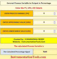
0–20 mA to Measurement Converter
0-20 mA Signal to Measurement Converter Formula
The relationship between the analog signal (current) and the measurement value is linear.
The formula to convert a given current (in mA) to measurement value is:
Measurement Value = Min + ((mA – 0) / 20) × (Max – Min)
Formula
Where:
- mA = the current signal received
- Min = minimum value of the measurement range
- Max = maximum value of the measurement range
Explanation of the Formula
Here’s how the expression works, line by line:
- (mA – 0) – Since the signal range starts at 0 mA, subtracting 0 simply gives you the actual current value above the minimum of the range. (If the range ever started at something else, this term would change.)
- (mA – 0) / 20 – Divide the measured current by the full-scale current (20 mA) to get the fraction of the span that the signal represents. This yields a value between 0 and 1 for normal operation.
- (Max – Min) – This is the engineering span, i.e., the total measurement range of the instrument (for example, 0–5 m, 0–25 bar, −50 °C to 150 °C, etc.).
- ((mA – 0) / 20) × (Max – Min) – Multiply the fractional current by the engineering span to scale the fraction into real engineering units.
- Min + … – Finally, add the minimum engineering value to shift the scaled result up to the correct starting point of the range.
This linear scaling assumes the transmitter and loop are calibrated, the signal is noise-free, and the process follows a linear relationship between current and the measured variable.
Key Terms to Know
| Term | Description |
|---|---|
| mA | Milliampere – the current signal sent from the sensor or transmitter |
| Min Value | The lowest value of the process measurement (e.g., 0 °C, 0 bar) |
| Max Value | The highest value of the process measurement (e.g., 100 °C, 10 bar) |
| Span | Difference between Max and Min (Max – Min) |
| Linear Scaling | Direct proportionality between current and process value |
How to Use the Tool
- Open the 0–20 mA to Measurement Calculator from InstrumentationTools.com
- Enter the Measured Current in mA (typically between 0 and 20)
- Enter the Min and Max measurement range of your sensor (in real-world units)
- Click the Calculate button
- The corresponding process value will be displayed below the button
✅ The calculator accepts values even outside the 0–20 mA range for simulation purposes.
10 Practical Examples
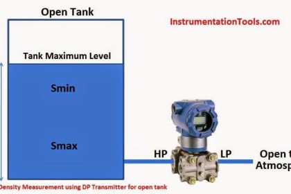
Example 1 – Tank Level Transmitter
Question: A level transmitter is calibrated so that 0–20 mA corresponds to 0–5.00 m of liquid. The PLC reads 13.0 mA. What is the actual tank level?
Solution:
Measurement = Min + ((mA – 0) / 20) × (Max – Min)
= 0 + ((13.0 – 0) / 20) × (5.00 – 0)
= 0 + (13.0 / 20) × 5.00
= 0 + 0.65 × 5.00
= 3.25 m
Example 2 – Boiler Drum Pressure
Question: A pressure transmitter uses a 0–20 mA range for 0–25 bar. The current signal is 6.8 mA. Determine the pressure.
Solution:
Measurement = 0 + ((6.8 – 0) / 20) × (25 – 0)
= (6.8 / 20) × 25
= 0.34 × 25
= 8.50 bar
Example 3 – Temperature with a Negative Minimum
Question: A temperature transmitter outputs 0–20 mA for −50 °C to 150 °C. It is sending 9.2 mA. What is the temperature?
Solution:
Measurement = −50 + ((9.2 – 0) / 20) × (150 – (−50))
= −50 + (9.2 / 20) × 200
= −50 + 0.46 × 200
= −50 + 92
= 42 °C
Example 4 – Flow Rate Measurement
Question: A flowmeter provides a 0–20 mA output for 0–1200 LPM. The signal is 17.5 mA. What is the flow rate?
Solution:
Measurement = 0 + ((17.5 – 0) / 20) × (1200 – 0)
= (17.5 / 20) × 1200
= 0.875 × 1200
= 1050 LPM
Example 5 – Control Valve Position Feedback
Question: A valve positioner sends 0–20 mA for 0–100 % valve opening. The analog input shows 2.4 mA. What is the valve position?
Solution:
Measurement = 0 + ((2.4 – 0) / 20) × (100 – 0)
= (2.4 / 20) × 100
= 0.12 × 100
= 12 % open
Example 6 – CO₂ Concentration in a Laboratory
Question: A CO₂ transmitter maps 0–20 mA to 300–1000 ppm. The controller reads 12.5 mA. What is the CO₂ level?
Solution:
Measurement = 300 + ((12.5 – 0) / 20) × (1000 – 300)
= 300 + (12.5 / 20) × 700
= 300 + 0.625 × 700
= 300 + 437.5
= 737.5 ppm
Example 7 – Relative Humidity Measurement
Question: A humidity transmitter scales 0–20 mA to 0–100 % RH. The current is 15.5 mA. Find the relative humidity.
Solution:
Measurement = 0 + ((15.5 – 0) / 20) × (100 – 0)
= (15.5 / 20) × 100
= 0.775 × 100
= 77.5 % RH
Example 8 – Fuel Tank Level with Non-Zero Minimum
Question: A level sensor outputs 0–20 mA for 1.20 m to 6.20 m. The measured signal is 15.0 mA. What is the level?
Solution:
Measurement = 1.20 + ((15.0 – 0) / 20) × (6.20 – 1.20)
= 1.20 + (15.0 / 20) × 5.00
= 1.20 + 0.75 × 5.00
= 1.20 + 3.75
= 4.95 m
Example 9 – Steam Flow Monitoring
Question: A steam flow transmitter uses 0–20 mA to represent 0–150 kg/h. The current value is 19.3 mA. Calculate the flow.
Solution:
Measurement = 0 + ((19.3 – 0) / 20) × (150 – 0)
= (19.3 / 20) × 150
= 0.965 × 150
= 144.75 kg/h
Example 10 – PLC Analog Input Scaling Verification
Question: A PLC analog input card receives 13.6 mA from a level transmitter where 0–20 mA = 0–5.0 m. What level should the HMI display?
Solution:
Measurement = 0 + ((13.6 – 0) / 20) × (5.0 – 0)
= (13.6 / 20) × 5.0
= 0.68 × 5.0
= 3.40 m
Benefits of Using This Calculator
- Saves manual calculation time
- Avoids scaling mistakes
- Helps during field instrumentation configuration
- Quick validation tool for troubleshooting current loops
- Useful for trainers, engineers, and students
- Allows input simulation for testing out-of-range values
Disadvantages or Limitations of the 0–20 mA Signal
| Limitation | Why It Matters |
|---|---|
| No live‑zero (0 mA = 0%) | A broken wire or failed transmitter also reads 0 mA, so the system cannot distinguish between “true zero” and “fault.” |
| Harder fault detection | PLC/DCS alarm logic must use timeouts or extra diagnostics to catch open-circuit conditions. |
| Cannot power 2‑wire transmitters | Most loop‑powered (2‑wire) devices are designed for 4–20 mA; 0–20 mA usually needs separate power. |
| More susceptible to ground/noise issues | With 0 mA allowed, tiny leakage currents or ground loops can skew readings without being obvious. |
| Less common in modern standards | Many contemporary controllers, safety PLCs, and smart instruments recommends 4–20 mA. |
| Scaling mistakes happen easily | Engineers may accidentally apply 4–20 mA formulas, causing wrong PV values. |
| No built‑in underrange alarm band | 0–20 mA does not provide under-range/fault diagnostics |
FAQ on 0–20 mA Signals
1. What exactly is a 0–20 mA signal?
A 0–20 mA signal is a linear analog current output from a field device (transmitter, sensor, positioner, etc.) where 0 mA represents the minimum (or zero) value of the measured variable and 20 mA represents the maximum value. Any current in between is proportional to the process value.
2. Why do some plants still use 0–20 mA instead of 4–20 mA?
Legacy systems, older PLC/indicator input cards, and simple bench instruments were designed around 0–20 mA. In such cases, keeping the same range avoids re-engineering. Also, for applications where wire-break detection is less critical, 0–20 mA is acceptable.
3. What is the main drawback of 0 mA at the low end?
No live-zero. A reading of 0 mA could mean “true zero process value” or a broken wire / dead transmitter. With 4–20 mA, anything below ~3.8 mA is a fault indication. In 0–20 mA loops you must add diagnostic logic (timers, limit checks) to catch faults.
4. How do I scale a 0–20 mA signal inside a PLC?
Use the same linear formula used by this tool:
Measurement = Min + ((mA – 0) / 20) × (Max – Min)
Most PLCs provide a SCALE or MAP instruction. You enter Raw Min = 0 mA, Raw Max = 20 mA, Eng Min = Min, Eng Max = Max.
5. Can I use negative engineering values with 0–20 mA?
Yes. The Min value in your span can be negative (e.g., −50 °C). The formula still works because it uses Min and Max explicitly. Just ensure the transmitter is configured to output 0 mA at that negative Min value.
6. How can I detect a cable break or transmitter failure with 0–20 mA?
The 0-20 mA was not designed to detect the cable break or failures.
If required, then you need extra logic (limited possibilities), for example:
- Alarm if the signal stays at exactly 0.00 mA for X seconds while the process should not be zero.
- Add a low-cut “sanity threshold” (e.g., <0.1 mA) to trigger fault alarms.
- Use heartbeat bits or redundant sensors if the application is critical.
7. Can I power a 2‑wire transmitter on a 0–20 mA loop?
Generally no. 2‑wire loop-powered devices are designed for 4–20 mA, where 4 mA supplies baseline power. A 0 mA loop cannot power a device. You’d need an externally powered (3‑wire/4‑wire) transmitter.
8. What happens if the current goes above 20 mA?
Over-range (e.g., 21–22 mA) can indicate the process is above Max OR a fault. Some transmitters intentionally drive >20 mA to flag over-scale. Check the datasheet: some PLC cards saturate and clip at their maximum input value.
9. How long can my 0–20 mA cable run be?
Current loops are naturally immune to voltage drop across distance—as long as loop power can drive the required voltage. Long runs add resistance; ensure the supply voltage headroom is enough (V = I×R). Also, twisted pair/shielded cable helps reject noise.
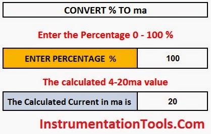
10. How do I convert 0–20 mA to a voltage for testing?
Place a precision resistor across the input and measure voltage:
V = I × R.
Example: With a 250 Ω resistor, 20 mA = 5 V. Use this to feed devices that only accept voltage or for oscilloscope/multimeter checks.
11. What ADC resolution do I need for accurate 0–20 mA readings?
Depends on the required accuracy. For example, a 12‑bit ADC over 0–20 mA gives 4096 counts ⇒ ~0.0049 mA/bit. If that translates to too coarse an engineering unit step, use higher-resolution ADCs or digital transmitters.
12. Can multiple devices share the same 0–20 mA signal?
A single current source should ideally drive one current input. Splitting the loop in series changes loop resistance; splitting in parallel causes incorrect current sharing. Use signal isolators/splitters if you need to feed multiple inputs.
13. How do I choose Min and Max correctly?
It is based on the instrument calibration range and process requirements. If your tank is 0–6 m, use that range. If the process seldom goes above 4 m, you might tighten the Max to improve resolution, but ensure the transmitter can be configured to match.
14. Is HART communication possible on 0–20 mA loops?
HART superimposes a digital signal onto the analog current. It technically works on 4–20 mA loops. On 0–20 mA, it is less common and may not be supported—check the transmitter’s manual. No live-zero also complicates HART power requirements.
15. How can I filter noise on a 0–20 mA input?
- Use shielded twisted pair cable and ground the shield at one end.
- Implement software filtering (moving average, low-pass) in the PLC.
- Keep analog cables away from high-voltage cables and VFD outputs.
Conclusion
The 0–20 mA Analog Signal to Measurement Reading Converter Tool is a valuable utility for anyone working with instrumentation systems. Whether you are configuring transmitters, validating DCS/PLC inputs, or simply learning about current loops, this tool simplifies your workflow.