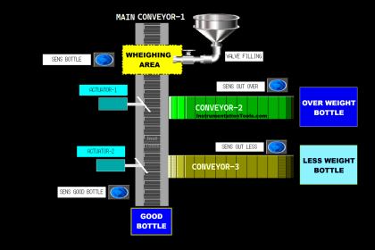
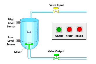
This article discusses the design of an automated product delivery system using four conveyor units controlled via Siemens TIA Portal. The system is designed to operate only when it detects the presence of a product, ensuring energy efficiency and performance. The four conveyors are interconnected with an interlock mechanism, allowing them to work alternately in a coordinated sequence. Additionally, the system is equipped with an automatic counter to record the number of products successfully delivered. As a safety measure, an alarm will be activated if no product is detected within a certain period.
Program Objective
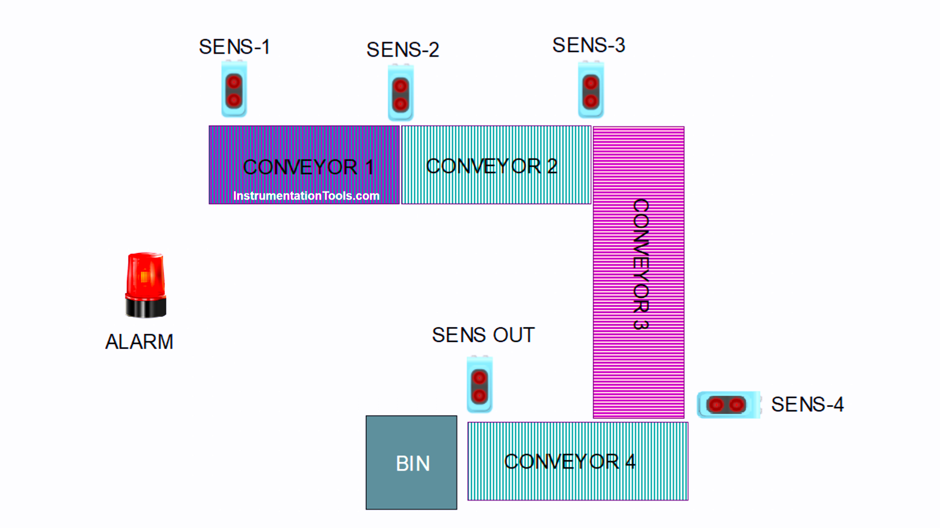
Automated Conveyor System Operation Procedure:
- Conveyor Activation
- Each conveyor will automatically turn on when the sensor detects a product.
- System Configuration
- There are 4 conveyor units in the system: Conveyor 1, 2, 3, and 4.
- System Warning (Alarm)
- If no product is detected for 6 seconds, a warning alarm will activate.
- Automatic Conveyor Stop
- The conveyor will stop running once the sensor no longer detects a product.
- Automatic Shutdown After Delivery
- All conveyors will automatically turn off after the product enters the collection bin.
- Product Counting
- The system records the number of successfully delivered products in real time.
- Counter Reset
- If the total number of products reaches 8, the counter will automatically reset to zero.
Siemens TIA Portal IO Mapping
| S.No. | Comment | Input (I) | Output (Q) | Memory Bit | Memory Words | Timers |
|---|---|---|---|---|---|---|
| 1 | START | I0.0 | ||||
| 2 | STOP | I0.1 | ||||
| 3 | SENS_1 | I0.2 | ||||
| 4 | SENS_2 | I0.3 | ||||
| 5 | SENS_3 | I0.4 | ||||
| 6 | SENS_4 | I0.5 | ||||
| 7 | SENS_OUT | I0.6 | ||||
| 8 | PB_RESET_COUNT | I0.7 | ||||
| 9 | CONVEYOR_1 | Q0.0 | ||||
| 10 | CONVEYOR_2 | Q0.1 | ||||
| 11 | CONVEYOR_3 | Q0.2 | ||||
| 12 | CONVEYOR_4 | Q0.3 | ||||
| 13 | ALARM | Q0.4 | ||||
| 14 | TIMER ALARM | DB1 | ||||
| 15 | SYSTEM_ON | M0.0 | ||||
| 16 | TEMP_SENS_1 | M0.1 | ||||
| 17 | TEMP_SENS_2 | M0.2 | ||||
| 18 | TEMP_SENS_3 | M0.3 | ||||
| 19 | TEMP_SENS_4 | M0.4 | ||||
| 20 | TEMP_SENS_OUT | M0.5 | ||||
| 21 | COUNT_PRODUCT | MW2 |
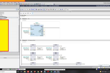
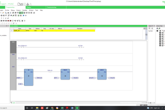
Automated Product Delivery System
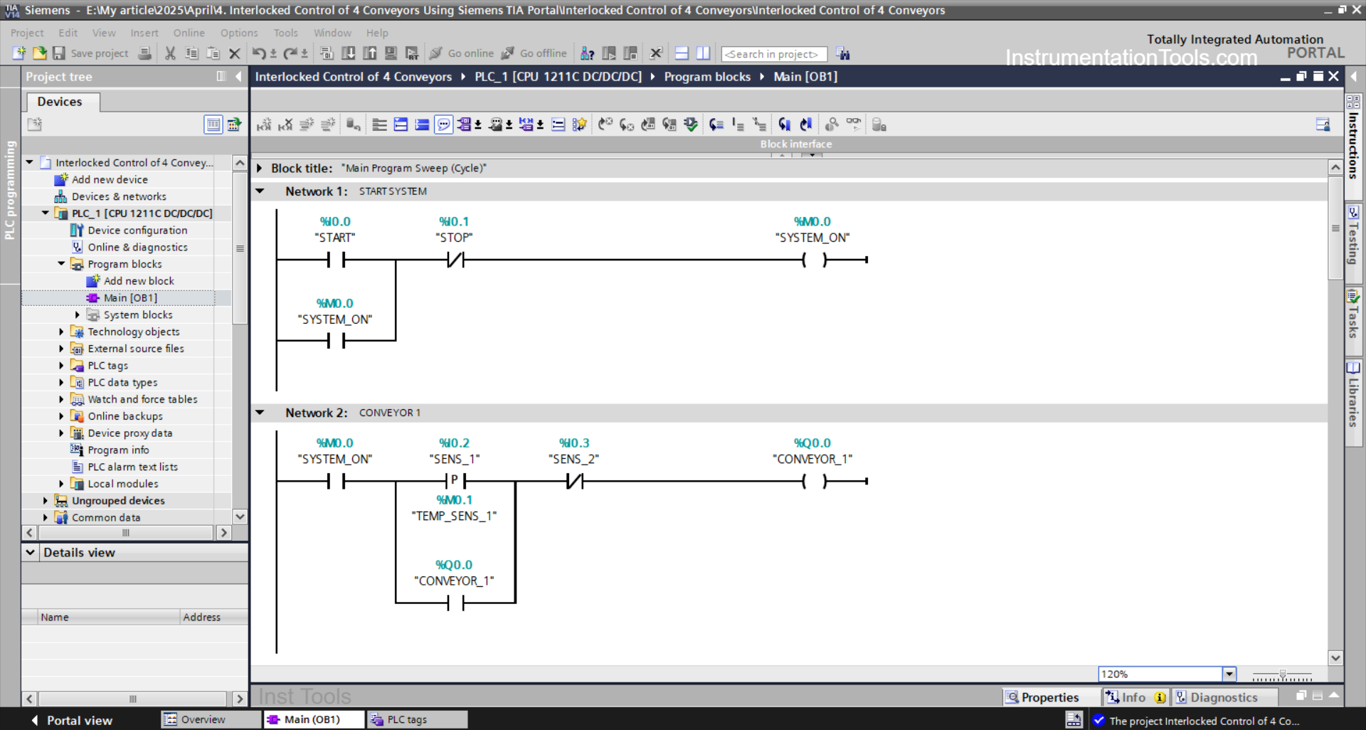
NETWORK 1 (START SYSTEM)
In this Network, the memory bit SYSTEM_ON (M0.0) will be in a HIGH state if the START (I0.0) button is pressed. The memory bit SYSTEM_ON (M0.0) will remain in a HIGH state even though the PB_START (I0.0) button has been released. Because it uses Latching.
If the STOP (I0.1) button is pressed, the memory bit SYSTEM_ON (M0.0) will return to a LOW state.
NETWORK 2 (CONVEYOR 1)
In this Network, the CONVEYOR_1 (Q0.0) output will be ON if the NO contact of the memory bit SYSTEM_ON (M0.0) and the SENS_1 (I0.2) sensor are in a HIGH state. the CONVEYOR_1 (Q0.0) output will remain ON even though the SENS_1 (I0.2) sensor is in the HIGH LOW state. Because it uses Latching.
When the NC contact of the SENS_2 (I0.3) sensor is in the HIGH state, the CONVEYOR_1 (Q0.0) output will return to OFF.

NETWORK 3 (CONVEYOR 2)
In this Network, the CONVEYOR_2 (Q0.1) output will be ON if the NO contact of the memory bit SYSTEM_ON (M0.0) and the SENS_2 (I0.3) sensor are in the HIGH state. The CONVEYOR_2 (Q0.1) output will remain ON even though the SENS_2 (I0.3) sensor is in the LOW state. Because it uses latching.
When the NC contact of the SENS_3 (I0.4) sensor is in the HIGH state, the CONVEYOR_2 (Q0.1) output will return to OFF.
NETWORK 4 (CONVEYOR 3)
In this Network, the CONVEYOR_3 (Q0.2) output will be ON if the NO contact of the memory bit SYSTEM_ON (M0.0) and the SENS_3 (I0.4) sensor are in the HIGH state. The CONVEYOR_3 (Q0.2) output will remain ON even though the SENS_3 (I0.4) sensor is in the LOW state. Because it uses Latching.
When the NC contact of the SENS_4 (I0.5) sensor is in the HIGH state, the CONVEYOR_3 (Q0.2) output will return to OFF.
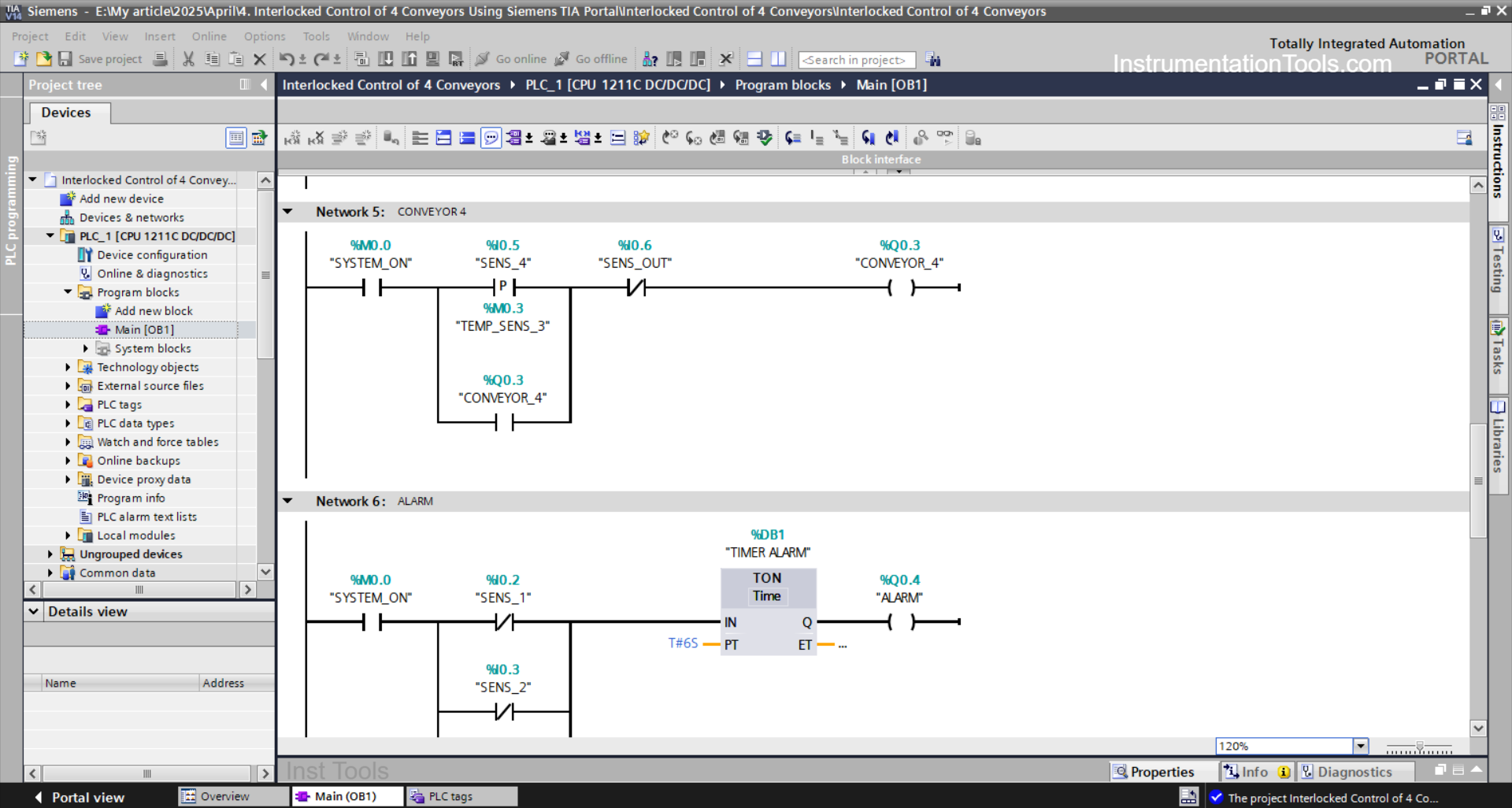
NETWORK 5 (CONVEYOR 4)
In this Network, the CONVEYOR_4 (Q0.3) output will be ON if the NO contact of the memory bit SYSTEM_ON (M0.0) and the SENS_4 (I0.5) sensor are in the HIGH state. The CONVEYOR_4 (Q0.3) output will remain ON even though the SENS_4 (I0.5) sensor is in the LOW state. Because it uses Latching.
When the NC contact of the SENS_OUT (I0.6) sensor is in the HIGH state, the CONVEYOR_4 (Q0.3) output will return to OFF.
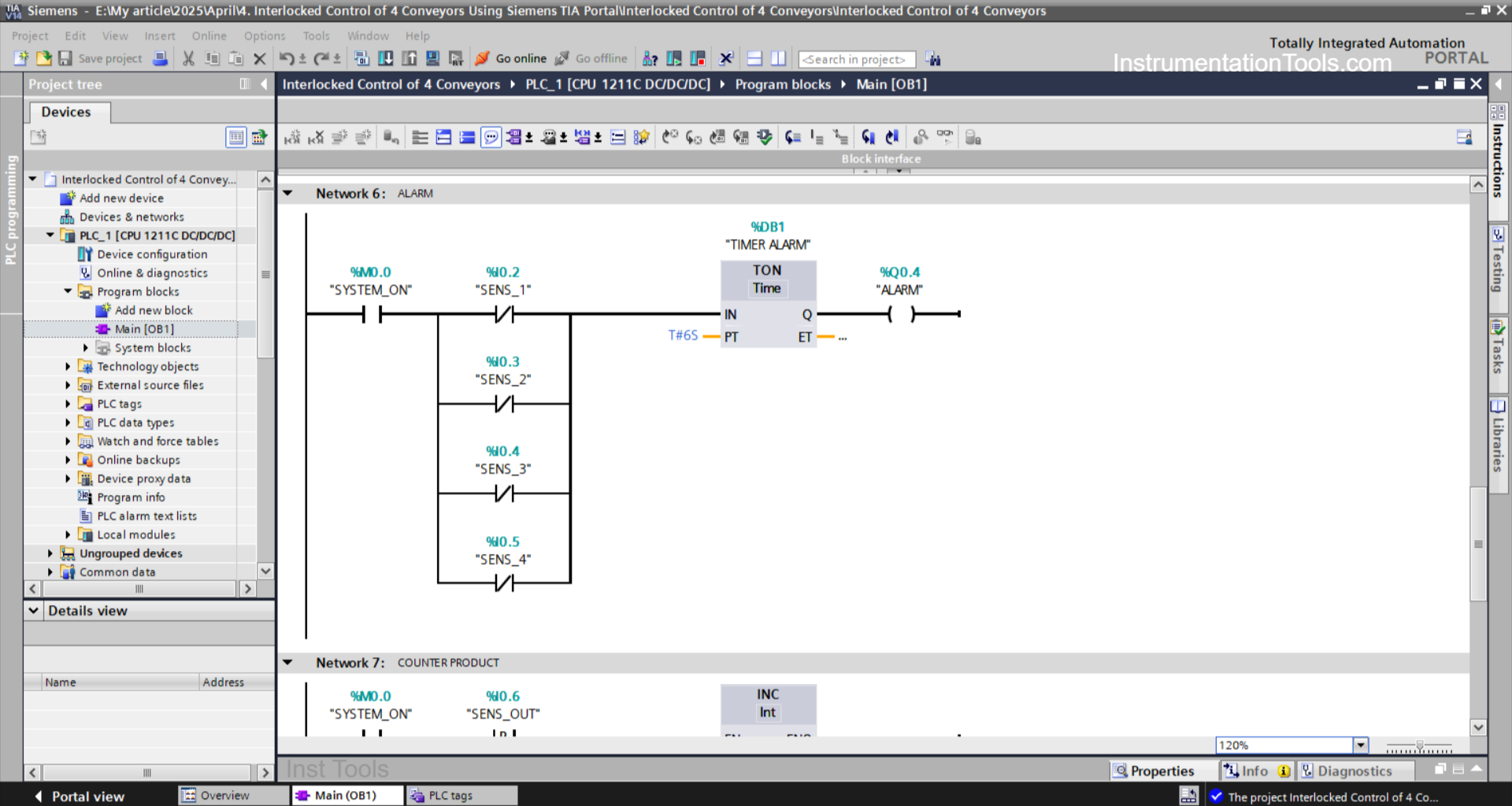
NETWORK 6 (ALARM)
In this Network, the TIMER ALARM (DB1) timer will start counting up to 6 seconds when the NO contact of the memory bit SYSTEM_ON (M0.0) is in the HIGH state.
The ALARM (Q0.4) output will be ON when the TIMER ALARM (DB1) timer has finished counting.
The ALARM (Q0.4) output will be OFF and the timer TIMER ALARM (DB1) will be reset, if any NC contact from the sensors SENS_1 (I0.2), SENS_2 (I0.3), SENS_3 (I0.4), SENS_4 (I0.5) is in the HIGH state.
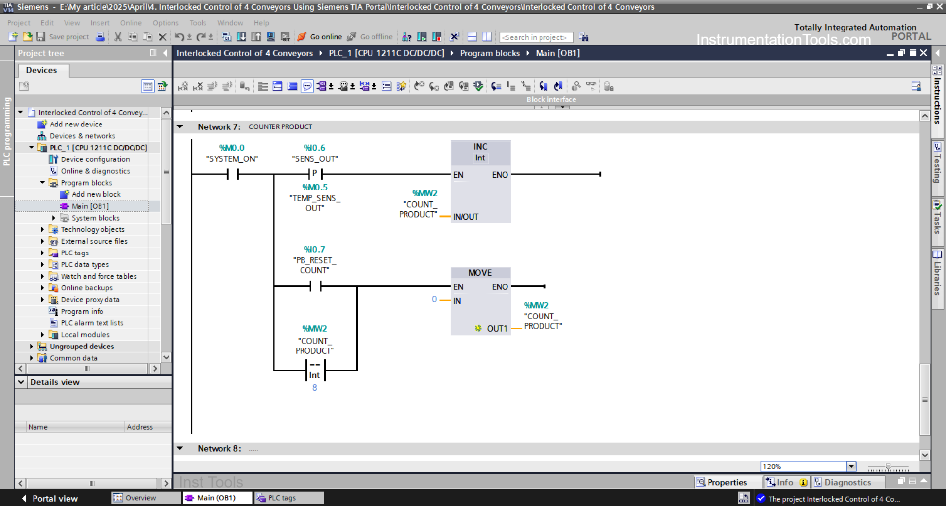
NETWORK 7 (COUNTER PRODUCT)
In this Network, the value of the memory word COUNT_PRODUCT (MW2) will increase (+1) if the NO contact of the memory bit SYSTEM_ON (M0.0) and the SENS_OUT(I0.6) sensor are in the HIGH state. Because it uses the Increment instruction.
The value of the memory word COUNT_PRODUCT (MW2) will be reset to “0” when the value of the memory word COUNT_PRODUCT (MW2) is Equal to “8” or the PB_RESET_COUNT (I0.7) button has been pressed.
Read Next:
- Top 5 Cybersecurity Threats to Safety PLC
- What is Dead Zero Problem in Analog Signals?
- SIMATIC PLC Program for Aquaculture System
- Liquid Transfer Between Two Tanks Using TIA
- STEP 7 PLC for Liquid Level Alarm and Control