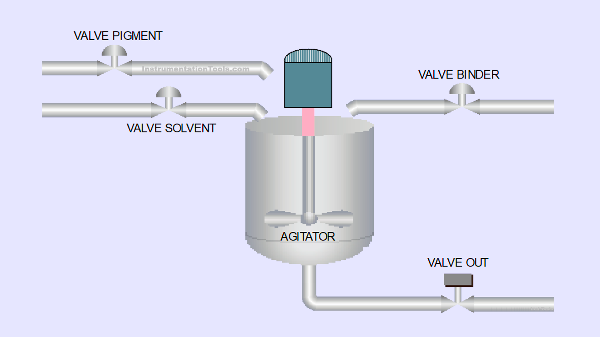
This article will explain the paint mixing system using Siemens TIA-Portal software. The system is designed to automate the process of filling and mixing paint materials to ensure accurate blending according to predefined measurements based on time. The system is equipped with an automatic counting feature to record each mixing process that has been performed. The system will also provide a warning alarm when the process is complete.
Program Objective
Here are the control system logic steps:
- System Activation: The system will start operating only when the Start button is pressed.
- Stage 1 – Pigment Filling: The pigment filling process runs for 6 seconds.
- Stage 2 – Solvent Filling: The solvent filling process runs for 4 seconds.
- Stage 3 – Binder Filling: The binder filling process runs for 6 seconds.
- Stage 4 – Mixing Process: The materials are mixed for 7 seconds by activating the Agitator.
- Process Completion Indicator: After the process is completed, the indicator light will turn On to signal the end of the operation.
- Process Counting: The system automatically counts the number of mixing processes performed.
- Tank Emptying: The tank can only be emptied manually by pressing the Valve Out button.
- System Reset: The indicator light will turn Off, and the system will be ready for the next process when the Reset button is pressed.
IO Mapping in Tia Portal
| S.No. | Comment | Input (I) | Output (Q) | Timers | Memory Words | Memory Bit |
|---|---|---|---|---|---|---|
| 1 | PB_START | I0.0 | ||||
| 2 | PB_STOP | I0.1 | ||||
| 3 | PB_VALVE_OUT | I0.2 | ||||
| 4 | RESET_ALARM | I0.3 | ||||
| 5 | RESET_COUNT_PROCESS | I0.4 | ||||
| 6 | VALVE_PIGMENT | Q0.0 | ||||
| 7 | VALVE_SOLVENT | Q0.1 | ||||
| 8 | VALVE_BINDER | Q0.2 | ||||
| 9 | MIXER_AGITATOR | Q0.3 | ||||
| 10 | LAMP_ALARM | Q0.4 | ||||
| 11 | VALVE_OUT | Q0.5 | ||||
| 12 | TIMER_PIGMENT | DB1 | ||||
| 13 | TIMER_SOLVENT | DB2 | ||||
| 14 | TIMER_BINDER | DB3 | ||||
| 15 | TIMER_AGITATOR | DB4 | ||||
| 16 | COUNT_PROCESS | MW2 | ||||
| 17 | SYSTEM_ON | M0.0 | ||||
| 18 | IR_TIMER_AGITATOR | M0.1 | ||||
| 19 | TEMP_DATA | M0.2 | ||||
| 20 | IR_TIMER_BINDER | M0.3 | ||||
| 21 | IR_TIMER_PIGMENT | M0.4 | ||||
| 22 | IR_TIMER_SOLVENT | M0.5 |
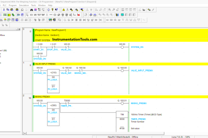
Paint Mixing System Control Program
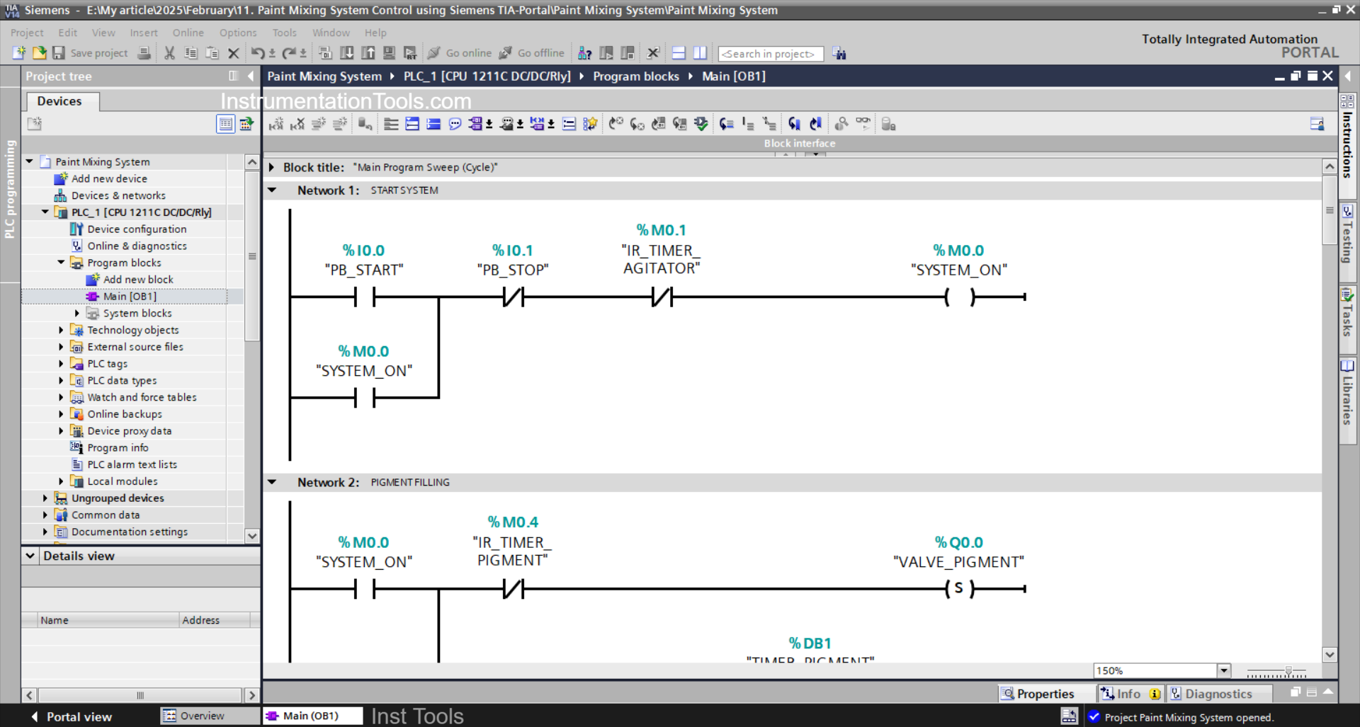
NETWORK 1 (START SYSTEM)
In this network, the memory bit SYSTEM_ON (M0.0) will be in the HIGH state if the PB_START (I0.0) button is Pressed. Because it uses Latching, even though the PB_START (I0.0) button has been released the memory bit SYSTEM_ON (M0.0) will remain in the HIGH state.
When the PB_STOP(I0.1) button has been Pressed or the NO contact of the memory bit IR_TIMER_AGITATOR (M0.1) is in the HIGH state, the memory bit SYSTEM_ON (M0.0) will be in the LOW state.
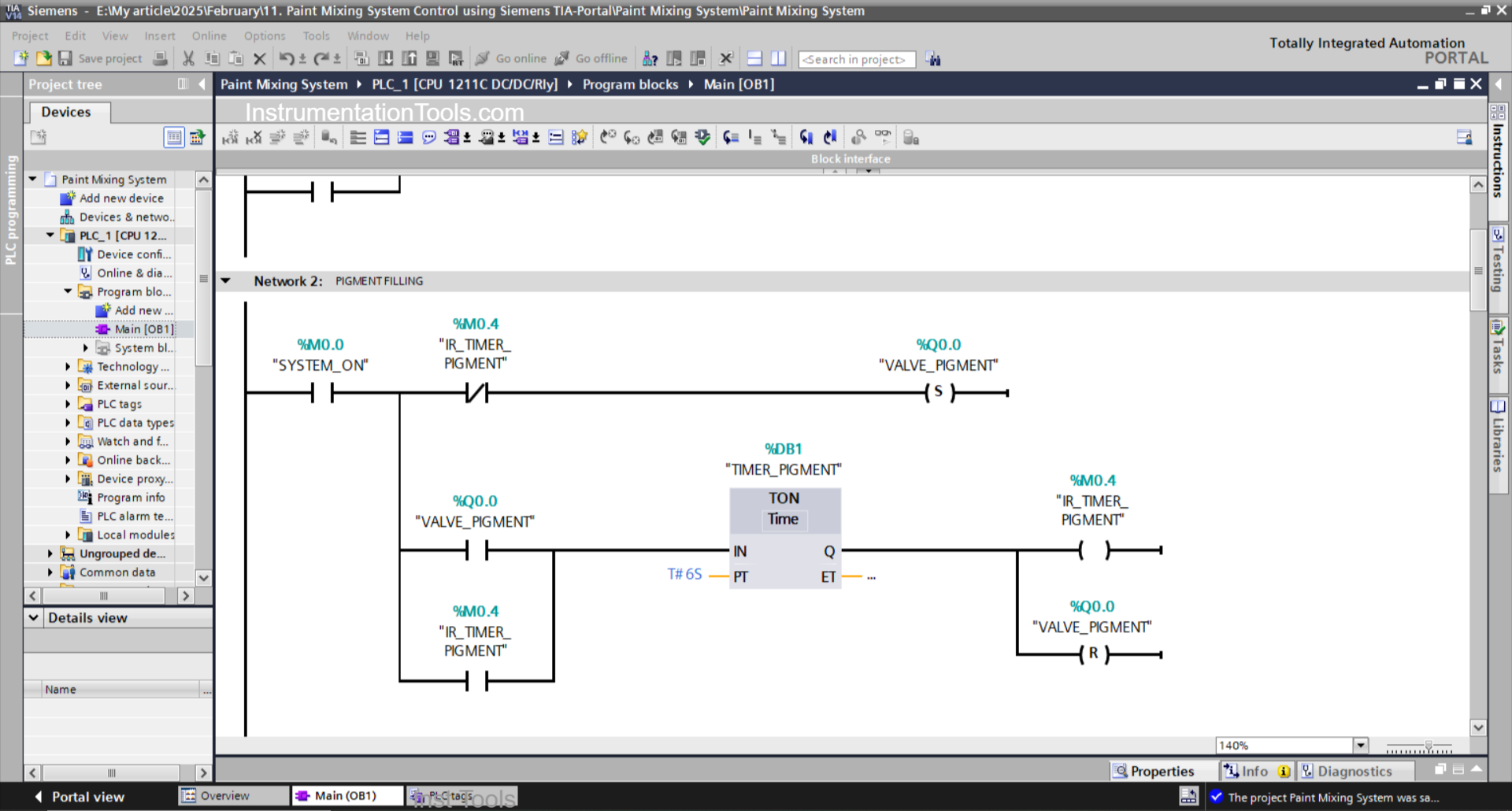
NETWORK 2 (PIGMENT FILLING)
In this network, when the NO contact of the memory bit SYSTEM_ON (M0.0) is in the HIGH state, the VALVE_PIGMENT (Q0.0) output will become OPEN.
The TIMER_PIGMENT (DB1) timer will start counting up to 6 seconds, and after the timer has finished counting, the memory bit IR_TIMER_PIGMENT (M0.4) will be in the HIGH state.
Next, the output VALVE_PIGMENT (Q0.0) will CLOSE due to the interlock from the memory bit IR_TIMER_PIGMENT (M0.4) and the RESET Output instruction triggered by the timer TIMER_PIGMENT (DB1).
The TIMER_PIGMENT (DB1) timer will remain ON because it uses Latching.
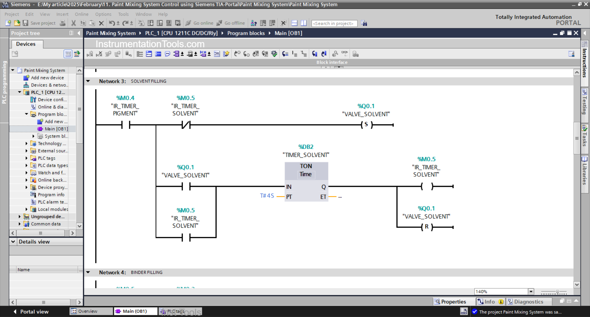
NETWORK 3 (SOLVENT FILLING)
In this network, when the NO contact of the memory bit IR_TIMER_PIGMENT (M0.4) is in the HIGH state, the VALVE_SOLVENT (Q0.1) output will be OPEN.
The TIMER_SOLVENT (DB2) timer will start counting up to 4 seconds, and after the timer has finished counting, the memory bit IR_TIMER_SOLVENT (M0.5) will be in the HIGH state.
Next, the output VALVE_SOLVENT (Q0.1) will CLOSE due to the interlock from the memory bit IR_TIMER_SOLVENT (M0.5) and the RESET Output instruction triggered by the timer TIMER_SOLVENT(DB2).
The TIMER_SOLVENT (DB2) timer will remain ON because it uses Latching.

NETWORK 4 (BINDER FILLING)
In this network, when the NO contact of the memory bit IR_TIMER_SOLVENT (M0.5) is in the HIGH state, the output VALVE_BINDER (Q0.2) will become OPEN.
The TIMER_BINDER (DB3) timer will start counting up to 6 seconds, and after the timer has finished counting, the memory bit IR_TIMER_BINDER (M0.3) will be in the HIGH state.
Next, the output VALVE_BINDER(Q0.2) will CLOSE due to the interlock from the memory bit IR_TIMER_BINDER(M0.3) and the RESET Output instruction triggered by the timer TIMER_BINDER (DB3).
The TIMER_BINDER (DB3) timer will remain ON because it uses Latching.
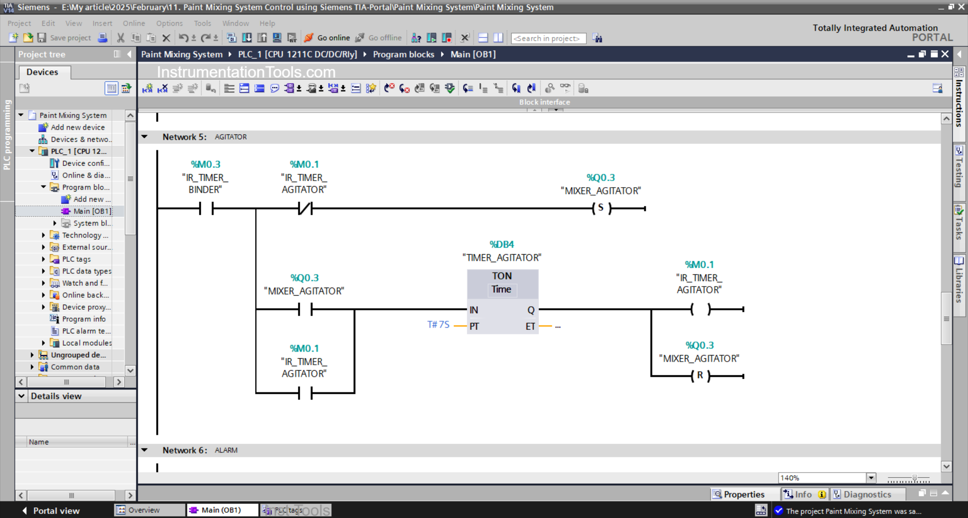
NETWORK 5 (MIXING PROCESS)
In this network, when the NO contact of the memory bit IR_TIMER_BINDER (M0.3) is in the HIGH state, the MIXER_AGITATOR (Q0.3) output will be ON.
TIMER_ AGITATOR (DB4) will start counting up to 7 seconds, and after the timer has finished counting, the memory bit IR_TIMER_AGITATOR (M0.1) will be in HIGH state.
Next, the output MIXER_AGITATOR(Q0.3) will be OFF due to the interlock from the memory bit IR_TIMER_AGITATOR(M0.1) and the RESET Output instruction triggered by the timer TIMER_AGITATOR (DB4).
The TIMER_ AGITATOR (DB4) timer will remain ON because it uses Latching.
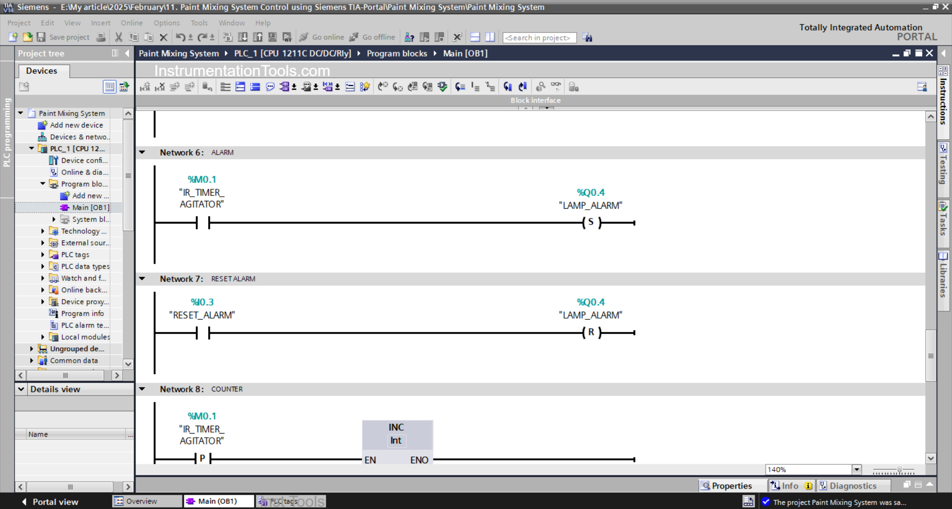
NETWORK 6 (ALARM)
In this network, when the NO contact of the memory bit IR_TIMER_AGITATOR (M0.1) is in the HIGH state, the LAMP_ALARM (Q0.4) output will be ON.
Because it uses the SET Output instruction, the LAMP_ALARM (Q0.4) output will remain ON even though the NO contact of the memory bit IR_TIMER_AGITATOR (M0.1) is in the LOW state.
NETWORK 7 (RESET ALARM)
Because it uses the RESET Output instruction, when the RESET_ALARM (I0.3) button is Pressed, the LAMP_ALARM (Q0.4) output will be OFF.
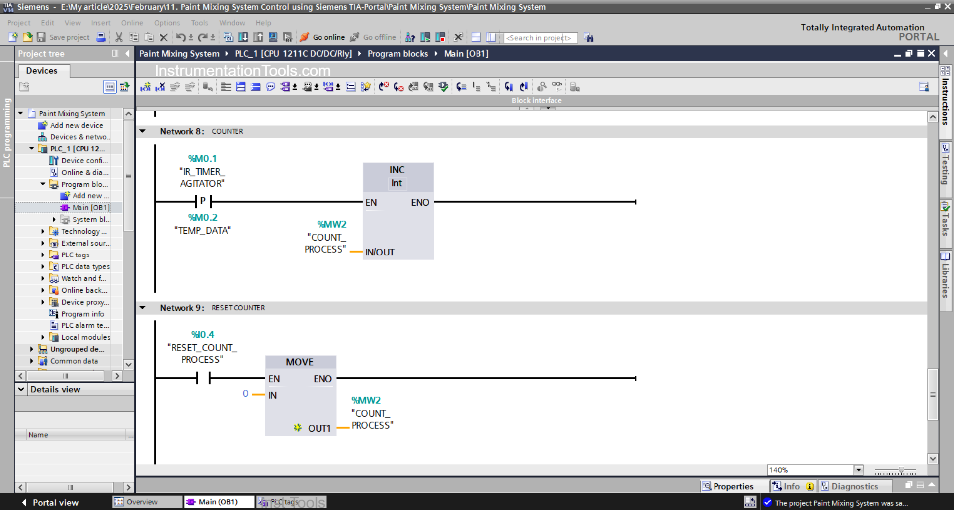
NETWORK 8 (COUNTER)
Because it uses the ADD instruction, when the NO contact of the memory bit IR_TIMER_AGITATOR (M0.1) is in the HIGH state, the value in the memory word COUNT_PROCESS (MW2) will increase (+1).
NETWORK 9 (RESET COUNTER)
Because it uses the MOV instruction, when the RESET_COUNT_PROCESS (I0.4) button is Pressed, the value in the memory word COUNT_PROCESS (MW2) will be reset to zero “0”.
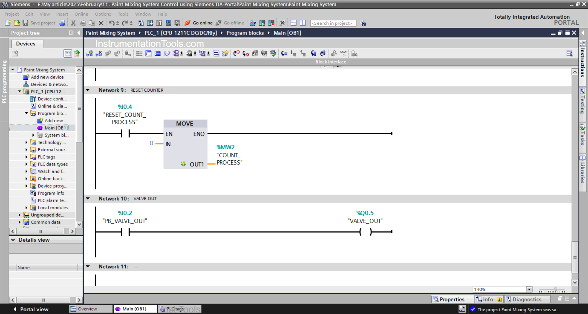
NETWORK 10 (VALVE OUT)
When the PB_VALVE_OUT (I0.2) button is Pressed, the VALVE_OUT (Q0.5) output will become OPEN.
Read Next:
- What are FIFO and LIFO Sequences in PLC?
- Difference Between Microcontroller and PLC
- Firmware Version of a Siemens PLC Hardware
- Tia Portal – OB30 Cyclic Interrupt Organization Block
- Tia Portal – OB20 Time Delay Interrupt Organization Block