This article discusses the PLC program for an automatic continuous liquid tank control logic using XG5000 PLC Software. The system is designed to control the continuous process of filling and draining liquid in a tank. The system will initiate the filling process when the liquid level in the tank reaches the minimum limit, and it will start the draining process when the liquid reaches the maximum limit. The entire system can also be controlled manually.
Program Objective
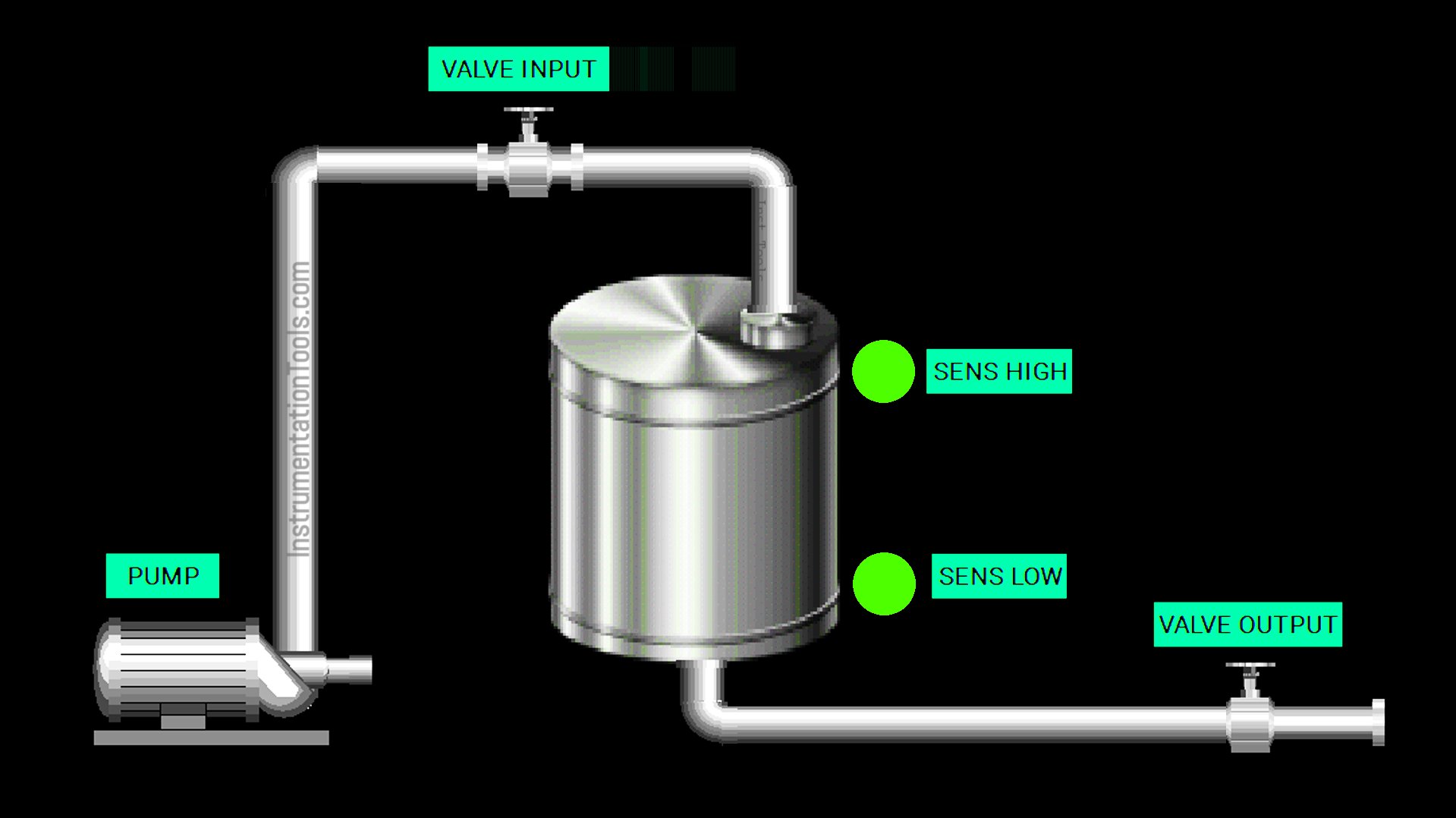
Step-by-Step System:
The system has 2 modes (Manual and Auto) that can be selected using a Selector Switch.
Auto Mode:
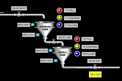
When the water level reaches the minimum limit, the LOW sensor will activate, and the filling process will begin. The Input Valve will open, and 2 seconds later, the pump will turn on. The Output Valve remains closed.
When the water level reaches the maximum limit, the HIGH sensor will activate, and the filling process will stop. The liquid drainage process will then begin. The Input Valve will close, and the pump will turn off. The Output Valve will open to drain the liquid from the tank.
The filling process will repeat continuously.
Manual Mode:
In manual mode, the Input Valve, Output Valve, and Pump can only be operated using buttons.
Continuous Liquid Tank Control Logic
IO Mapping
| S.No. | Comment | Input (I) | Output (Q) | Memory Bits | Timers |
|---|---|---|---|---|---|
| 1 | START | P0000 | |||
| 2 | STOP | P0001 | |||
| 3 | MODE | P0002 | |||
| 4 | PB_PUMP | P0003 | |||
| 5 | PB_VALVE_IN | P0004 | |||
| 6 | PB_VALVE_OUT | P0005 | |||
| 7 | SENS_LOW | P0006 | |||
| 8 | SENS_HIGH | P0007 | |||
| 9 | PUMP | P0040 | |||
| 10 | VALVE_IN | P0041 | |||
| 11 | VALVE_OUT | P0042 | |||
| 12 | SYSTEM_ON | M0000 | |||
| 13 | IR1_PUMP | M0001 | |||
| 14 | IR1_VALVE_IN | M0002 | |||
| 15 | IR1_VALVE_OUT | M0003 | |||
| 16 | IR2_PUMP | M0004 | |||
| 17 | IR2_VALVE_IN | M0005 | |||
| 18 | IR2_VALVE_OUT | M0006 | |||
| 19 | TIMER_PUMP | T000 |
XG5000 PLC Project
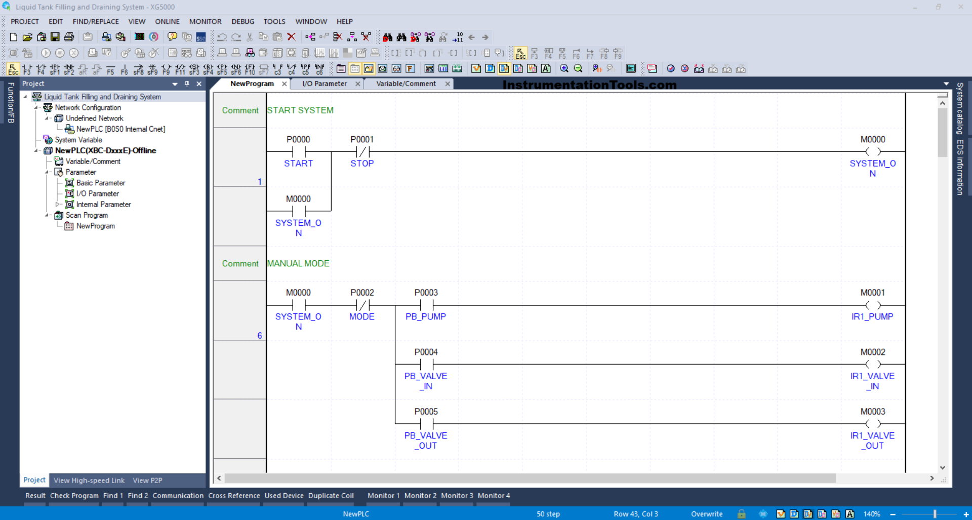
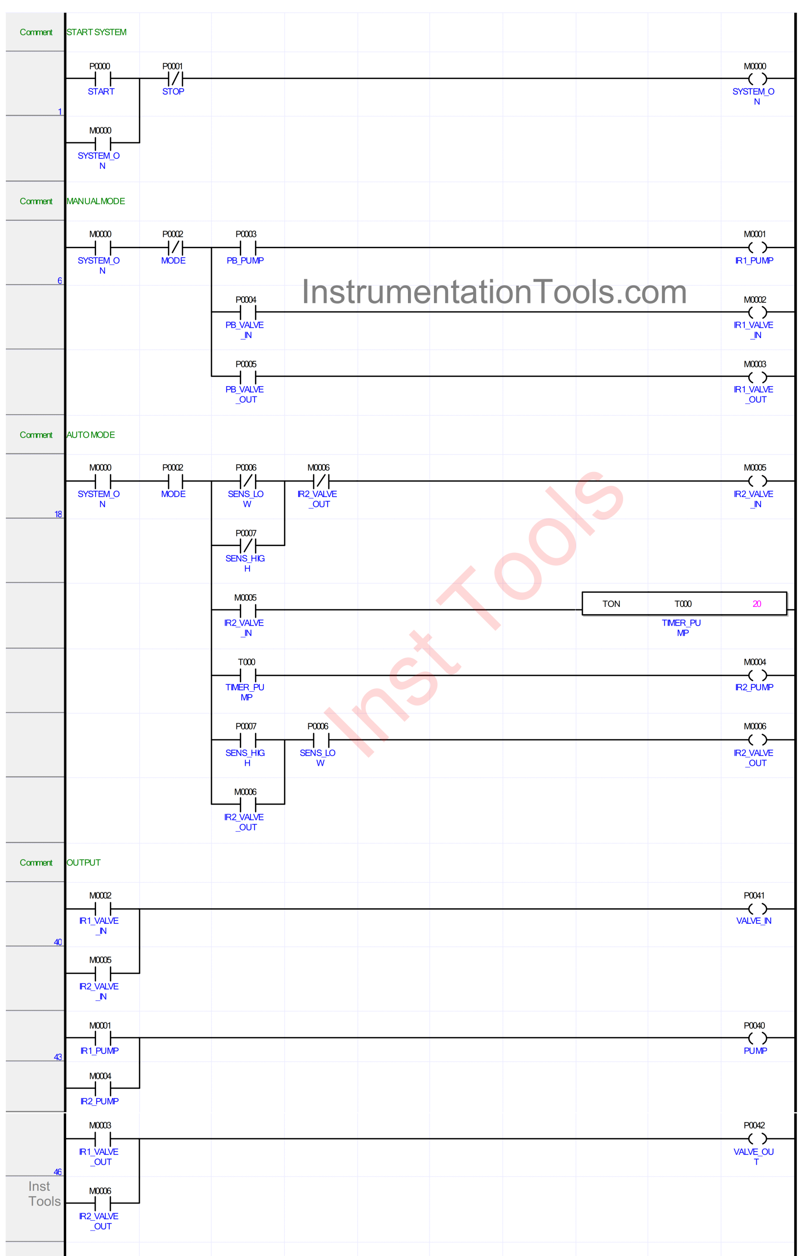
RUNG 1 (START SYSTEM)
In this Rung, when the START (P0000) button is pressed, the memory bit SYSTEM_ON (M0000) will be in the HIGH state. Because it uses Latching, the memory bit SYSTEM_ON (M0000) remains in the HIGH state even though the START (P0000) button has been released.
If the STOP (P0001) button is pressed, the memory bit SYSTEM_ON (M0000) will be in the LOW state.
RUNG 6 (MANUAL MODE)
When the NO contact of the memory bit SYSTEM_ON (M0000) is in the HIGH state and the PB_PUMP (P0003) button is pressed, the memory bit IR1_PUMP (M0001) will be in the HIGH state.
When the PB_VALVE_IN (P0004) button is pressed, the memory bit IR1_VALVE_IN (M0002) will be in the HIGH state.
And, when the PB_VALVE_OUT (P0005) button is pressed, the memory bit IR1_VALVE_OUT (M0003) will be in the HIGH state.
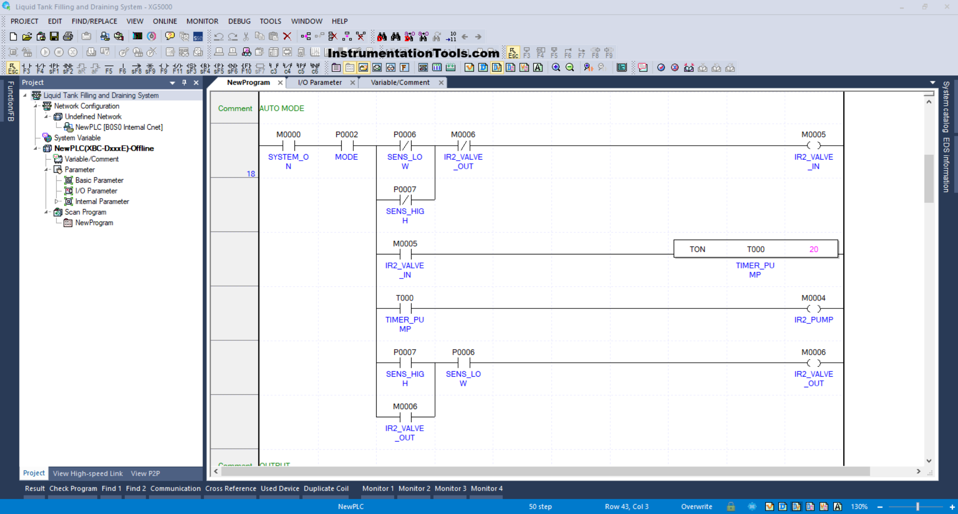
RUNG 18 (AUTO MODE)
In this Rung, when the NO contact of the memory bit SYSTEM_ON (M0000) and the MODE (P0002) selector switch are in the HIGH state and the NC contact of the SENS_LOW (P0006) and SENS_HIGH (P0007) sensors are in the LOW state, the memory bit IR2_VALVE_IN (M0005) will be in the HIGH state.
Next, the TIMER_PUMP (T000) timer starts counting up to 2 seconds, and after the timer finishes counting, the memory bit IR2_PUMP (M0006) will be in the HIGH state.
When the SENS_LOW (P0006) and SENS_HIGH (P0007) sensors are in the HIGH state, the memory bit IR2_VALVE_OUT (M0006) will be in the HIGH state.
The memory bit IR2_VALVE_IN (M0005) will return to the LOW state due to the Interlock from memory bit IR2_VALVE_OUT (M0006).
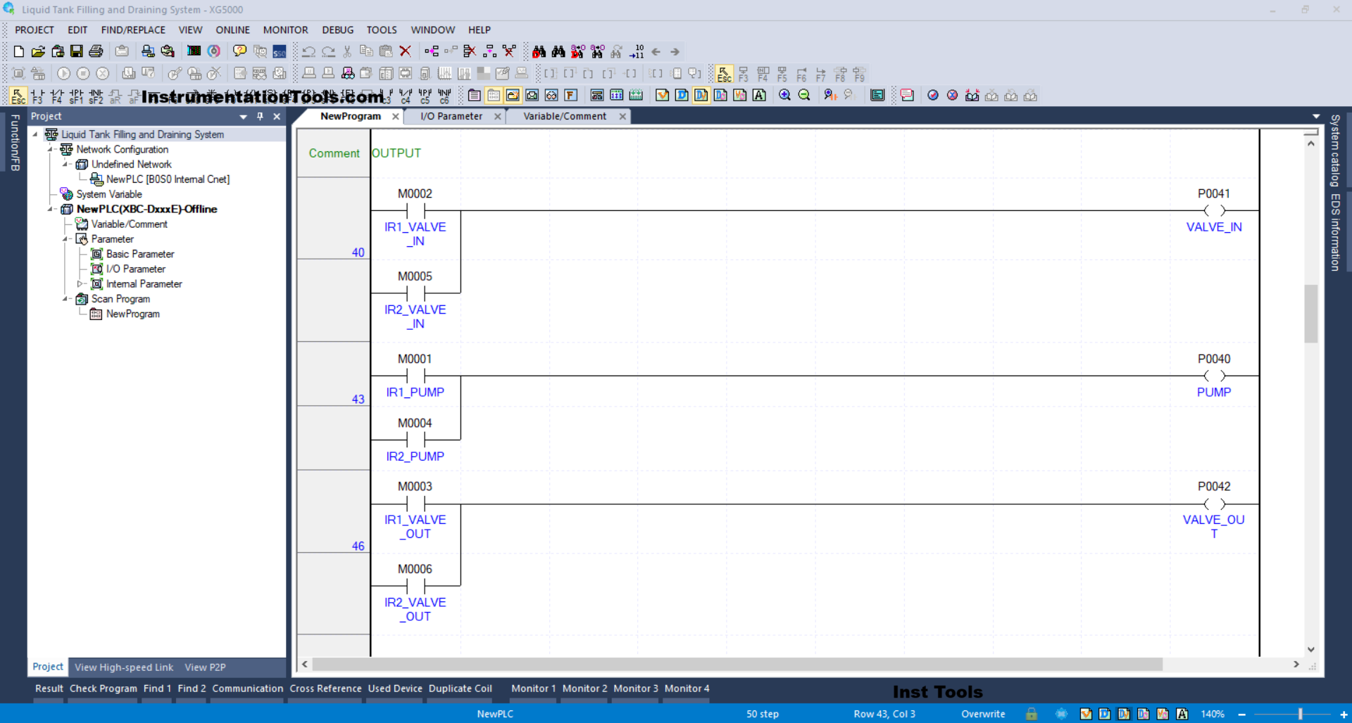
RUNG 40 (OUTPUT)
In this Rung, when the NO contact of the memory bits IR1_VALVE_IN (M0002) or IR2_VALVE_IN (M0002) is in the HIGH state, the VALVE_IN (P0041) output will be ON.
RUNG 43
In this Rung, when the NO contact of the memory bits IR1_PUMP (M0001) or IR2_PUMP (M0004) is in the HIGH state, the PUMP (P0040) output will be ON.
RUNG 46
In this Rung, when the NO contact of the memory bit IR1_VALVE_OUT (M0003) or IR2_VALVE_OUT (M0006) is in the HIGH state, the VALVE_OUT (P0042) output will be ON.
Read Next:
- PLC Example of Water Level-Based Pump Control
- Automatic Door Operation PLC Programming
- Sorting & Distribution Line PLC Programming
- How to Take a Backup from a Physical PLC?
- PLC Programming for Defective Parts Sorting