The motor is an output that is used in almost all industrial applications. Without a motor, there is literally no process that can work, because some force is required to move a process. Because motors are heavy-duty electrical outputs, they also require special care in electrical wiring for a safe and long-life operation.
When a PLC program is designed for operating the motor, some basic programming concepts are usually ignored by the programmer in a hurry. Such irregular design can hamper the performance of the system.
So, it is necessary to understand some general rules when you are programming a motor in PLC. In this post, we will see how to write a general PLC program for motor control using TIA Portal software.
Motor Starter Logic
Let us first understand the requirements for a motor starter logic:
- There must be critical interlocks for a motor present, like a control key, emergency stop, local-remote feedback, MCCB on feedback, and other types of safety signals. If any of these signals fails, then the motor will not run in any mode, be it auto or manual.
- To operate the motor from PLC in any mode, the starter switch must be selected in remote mode, and not local mode.
- The motor will run in manual mode from PLC when manual mode is selected. The push buttons for start and stop must be momentary in nature.
- The motor will run in auto mode from the PLC when auto mode is selected.
- There must be an on-delay timer for giving run commands to the motor.
- Generally, two alarms are checked once the motor is running – run feedback and trip. If any of these alarms occur, then too the motor will not run in any mode. The operator will first check and then reset these alarms.
- There should be a running hour display for the motor.
- There should be a status indication of the motor (running, stopped, or tripped).
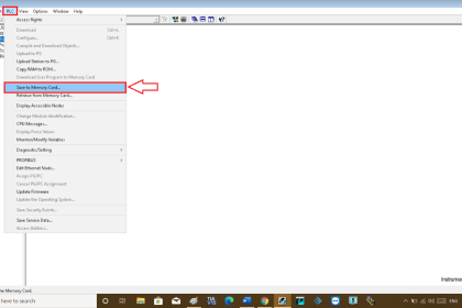
Siemens PLC Tia Portal
Now, let us how to write the logic accordingly rung by rung in TIA Portal:
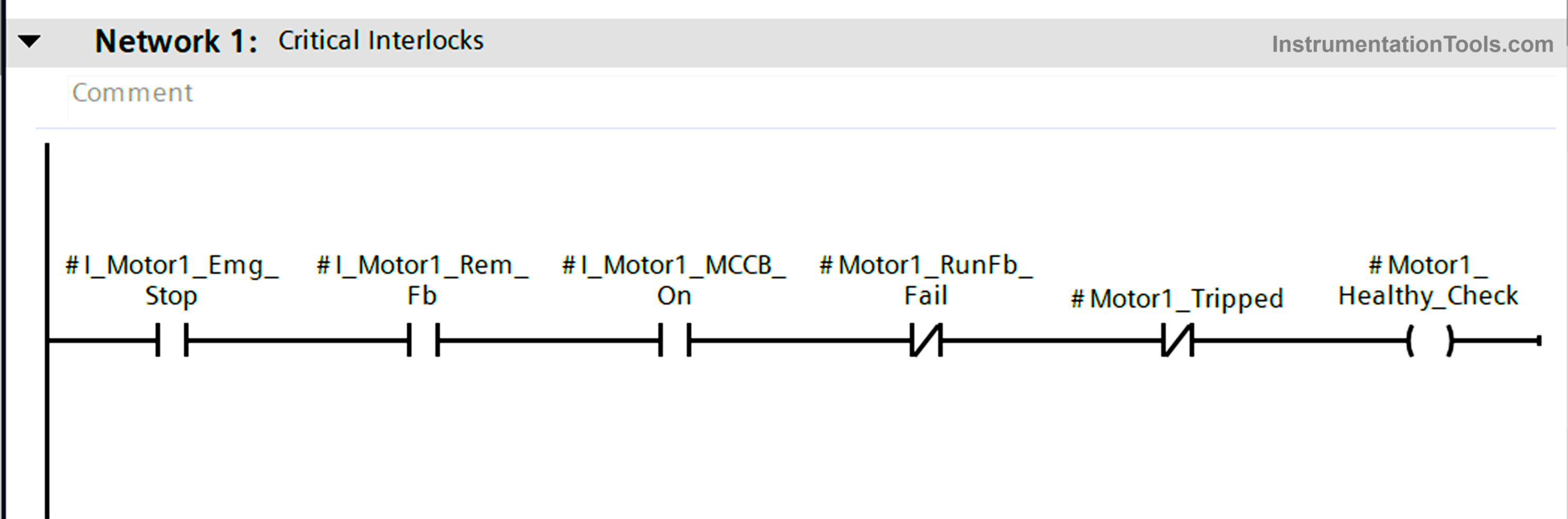
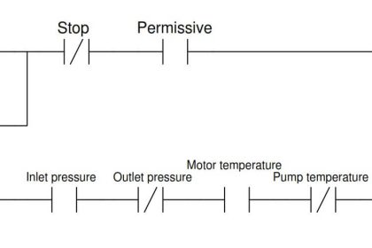
In this first image, we create a logic for all the critical signals and alarms considered a healthy condition for the motor. For that, we have taken all the elements in series, so that whichever input fails, the whole healthiness will be cut off.
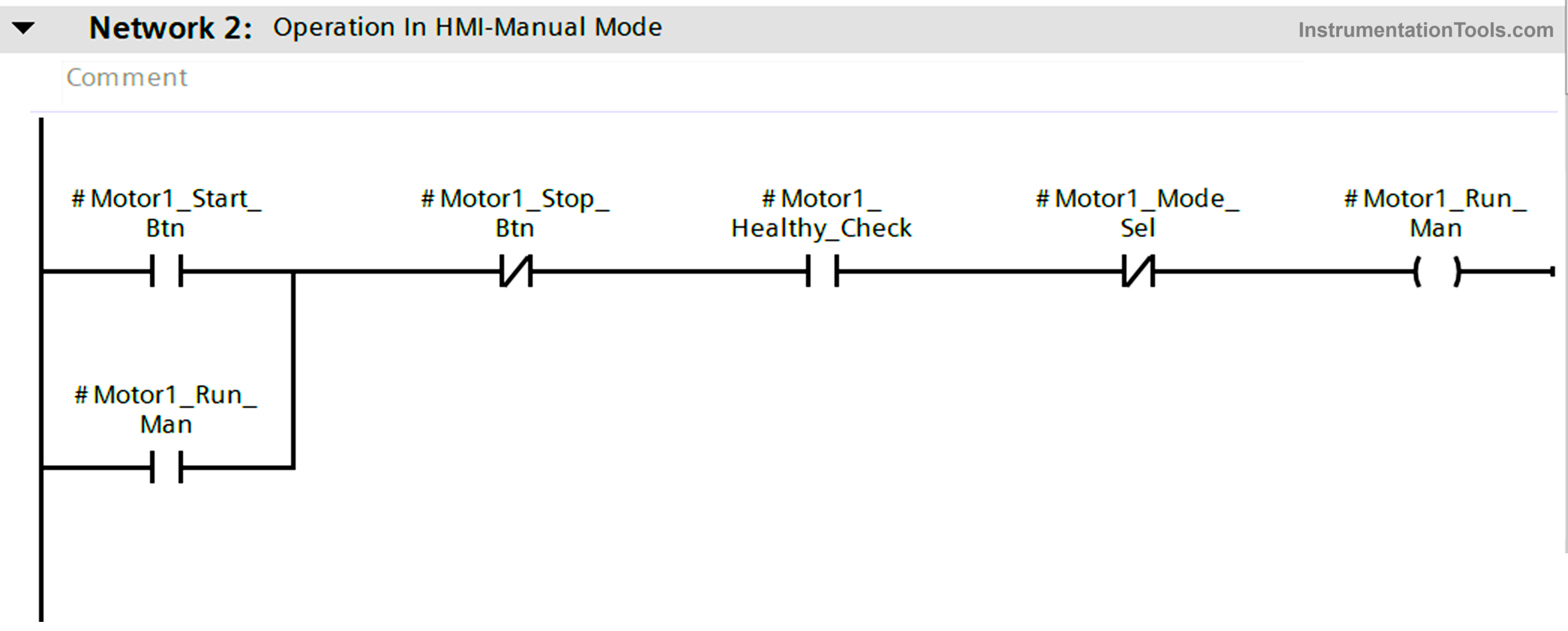
In the second image, we will operate the motor in manual mode. The motor will stop running in manual mode if the stop button is pressed, or auto mode is selected, or the motor becomes unhealthy to run.
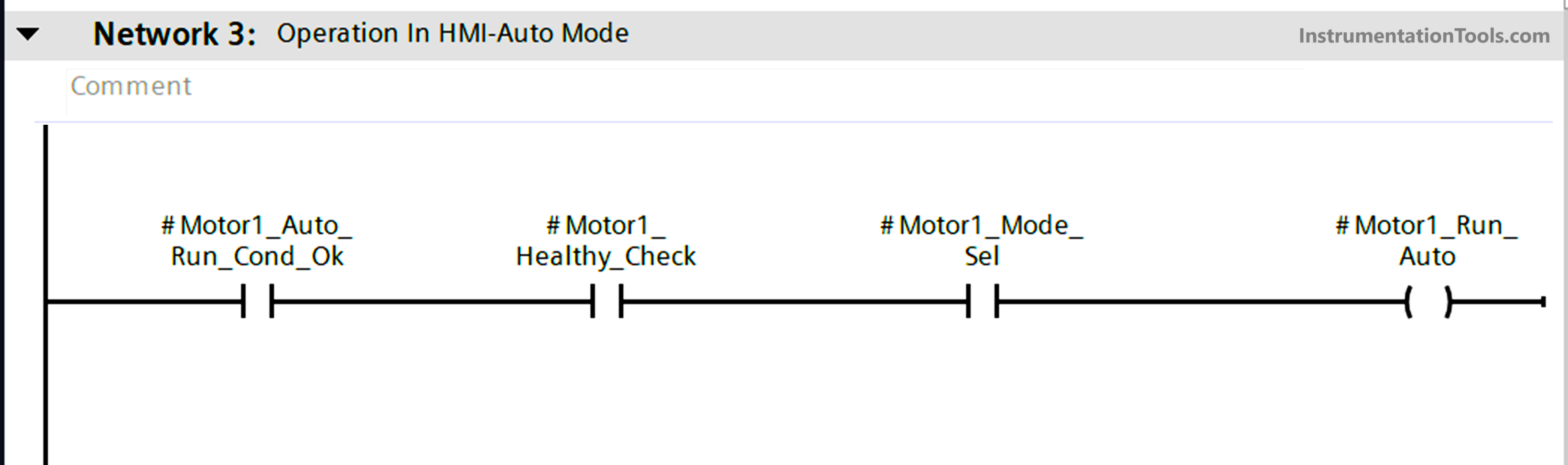
In the third image, we will operate the motor in auto mode. The motor will stop running in auto mode if the run command from auto logic becomes off, or manual mode is selected, or the motor becomes unhealthy to run.
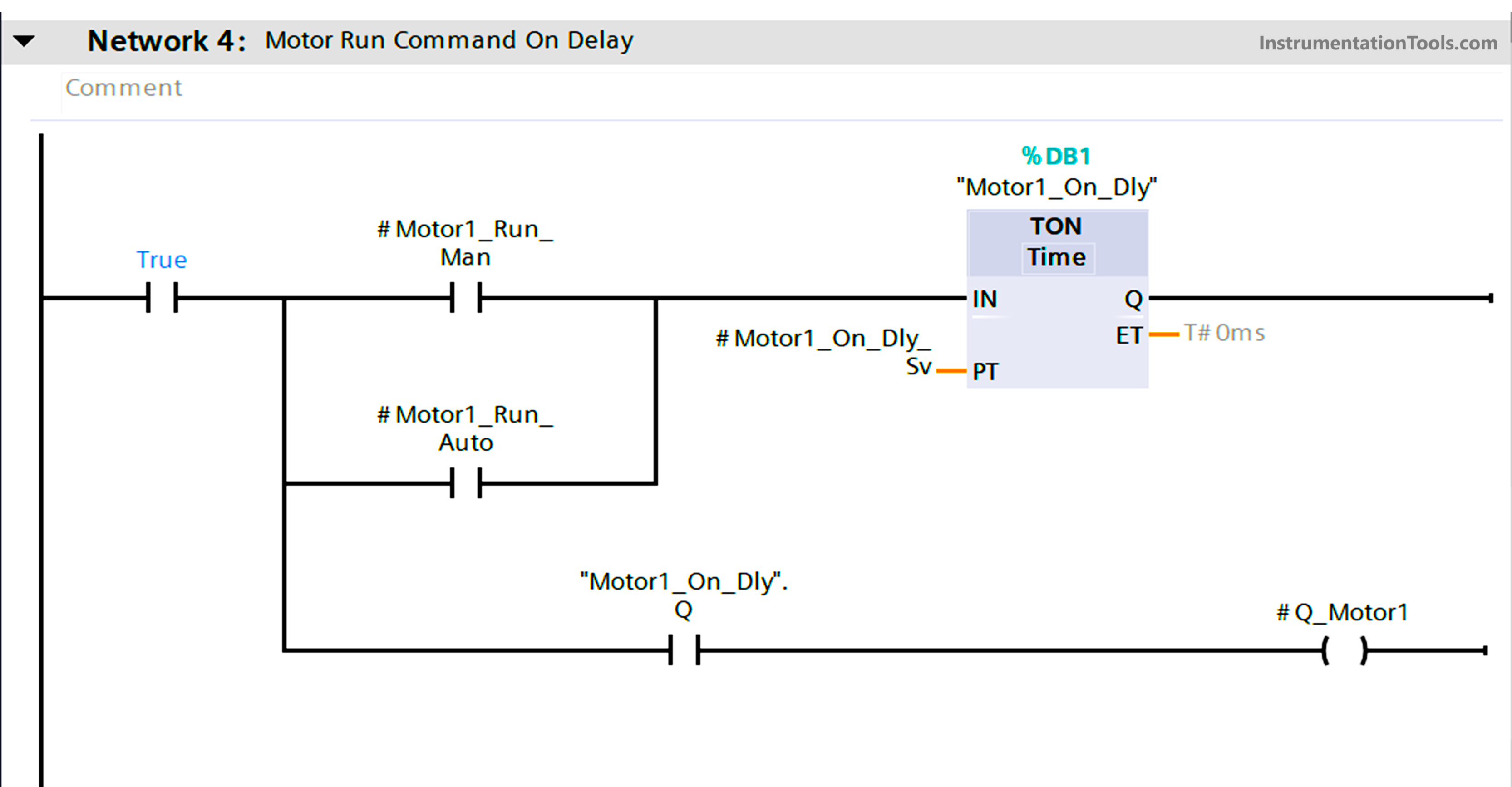
In the fourth image, we will give an on-delay timer for the motor to run in either manual run command or auto run command.
The on-delay timer will be settable, and not pre-fixed. This gives flexibility to commissioning engineers according to the site’s prevailing conditions and process parameters.
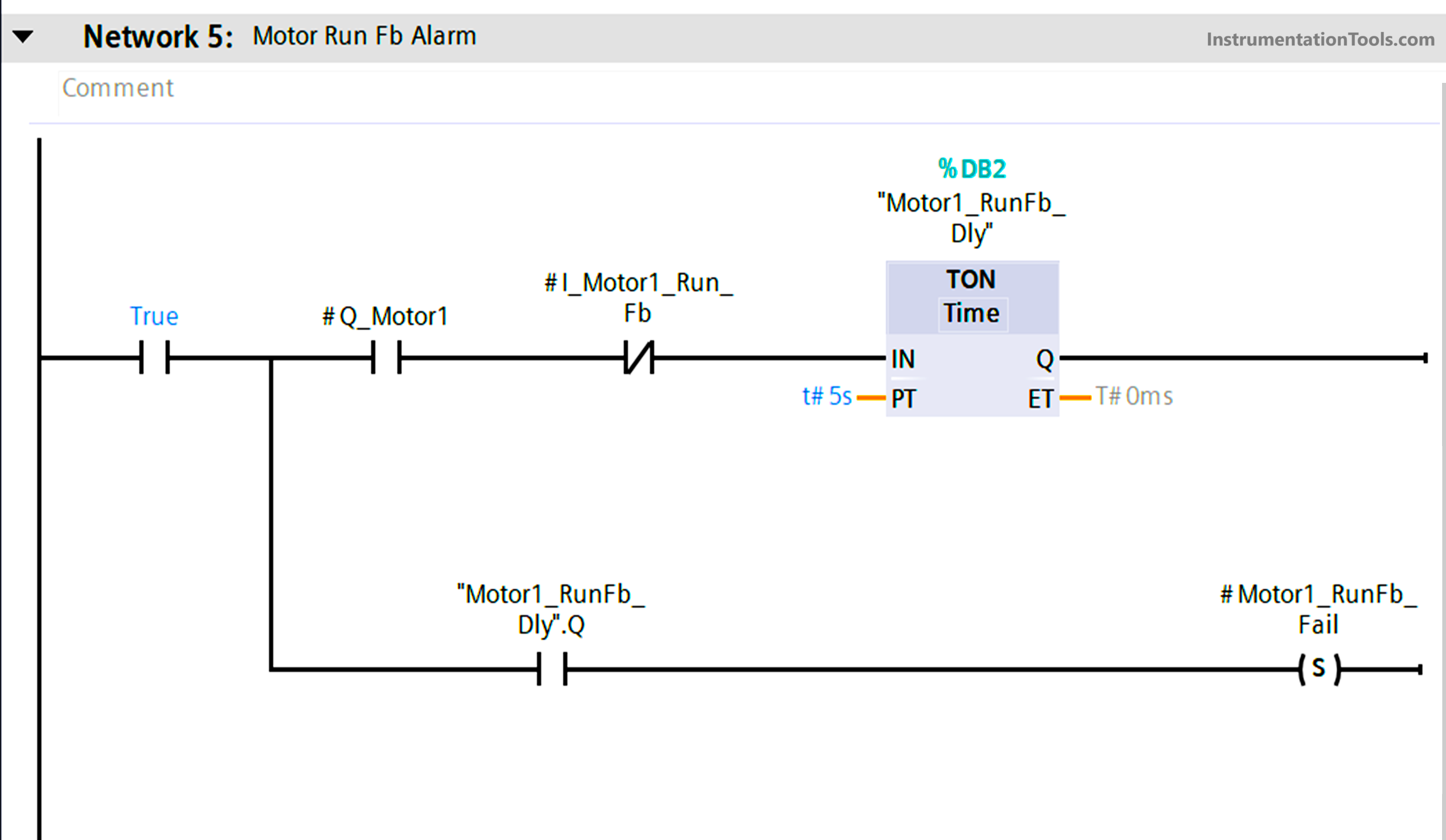
In the fifth image, we will check the run feedback of the motor for 5 seconds. If the PLC output is on and still the run feedback input is not received within this time, then an alarm will be generated and it will cut-off the motor run command; as taken in the first rung earlier. We will set this alarm bit so that it remains latched until operator intervention.
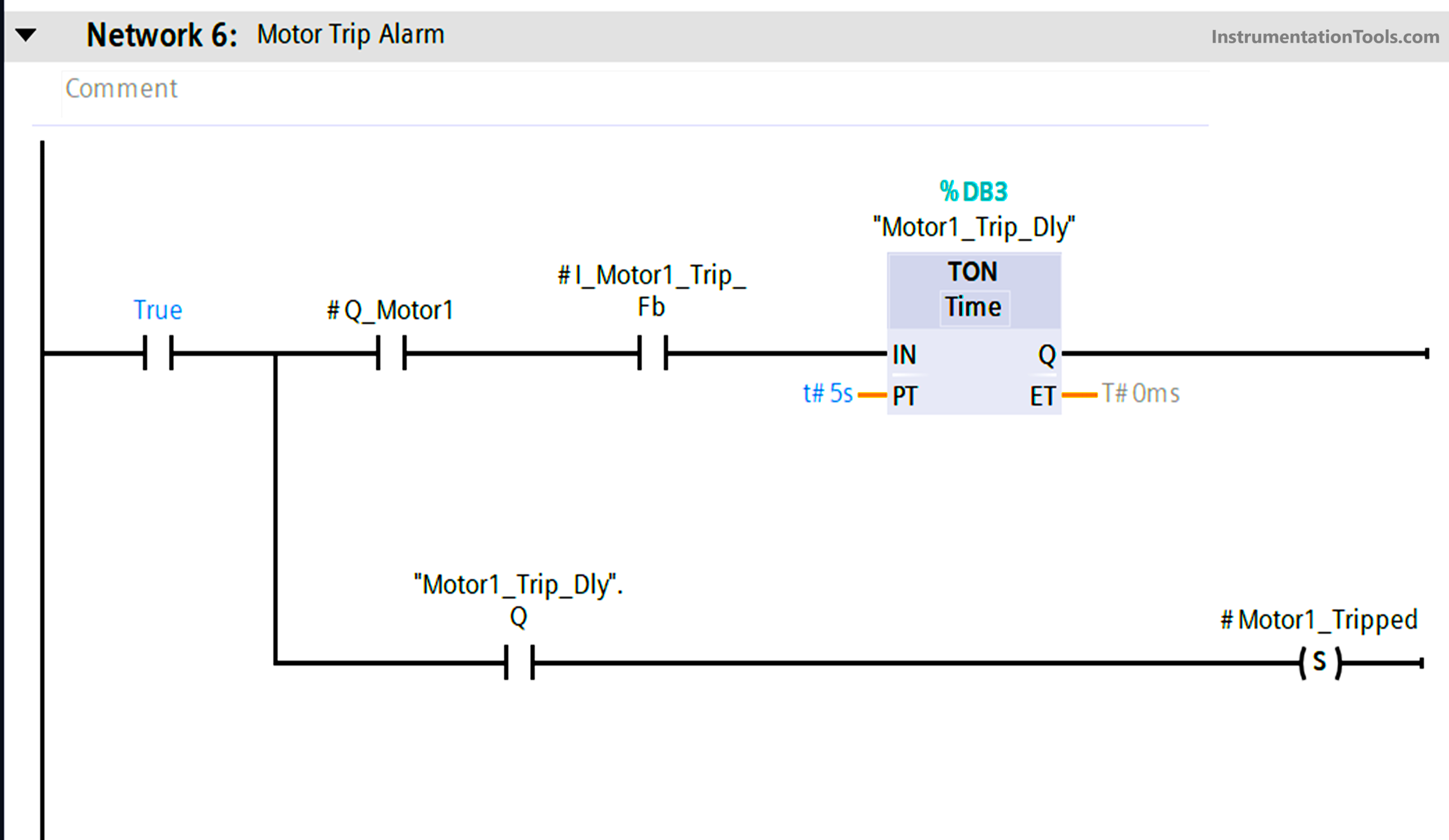
In the sixth image, we will check the trip feedback of the motor for 5 seconds.
If the PLC output is on and the trip feedback input is received within this time, then an alarm will be generated and it will cut-off the motor run command; as taken in the first rung earlier. We will set this alarm bit so that it remains latched until operator intervention.
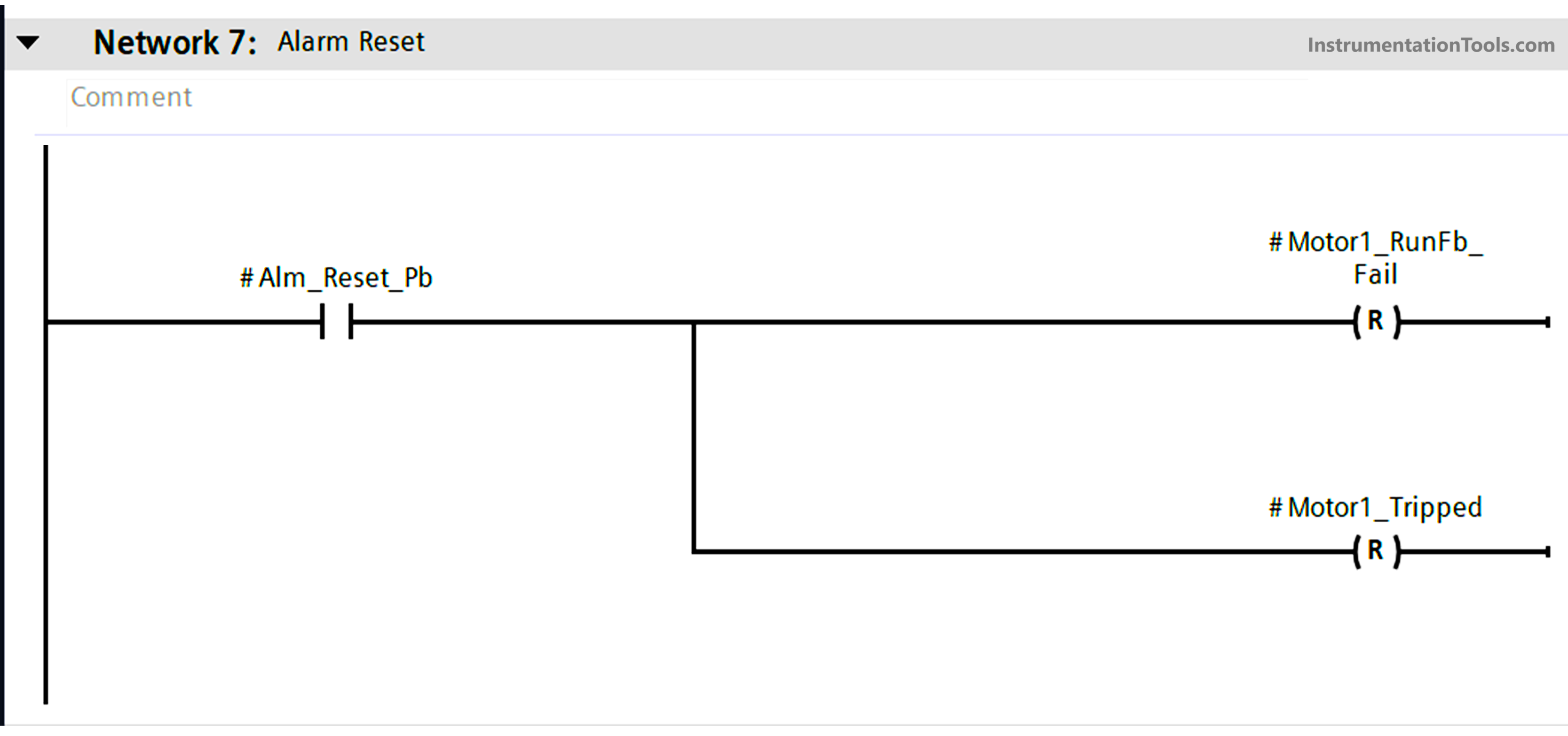
In the seventh image, we will reset these two alarms by pressing the reset button.
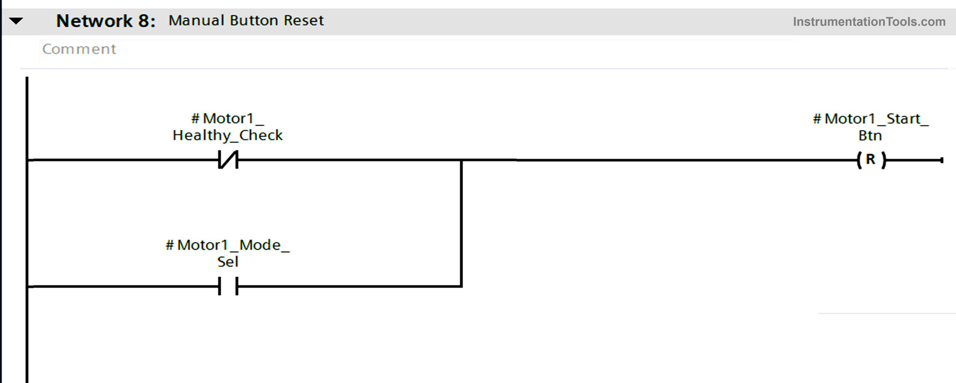
In PLC programming, a common error most forget to write is resetting the buttons. Now, we are not starting the motor in manual mode unless its conditions are met.
But what happens if then too someone presses the start button? The output will not turn on, but once the condition becomes healthy, the motor can start immediately.
This is because the start button can remain on if someone forgets to turn it off. So, to prevent this, we reset the manual push button if all the conditions are not met.
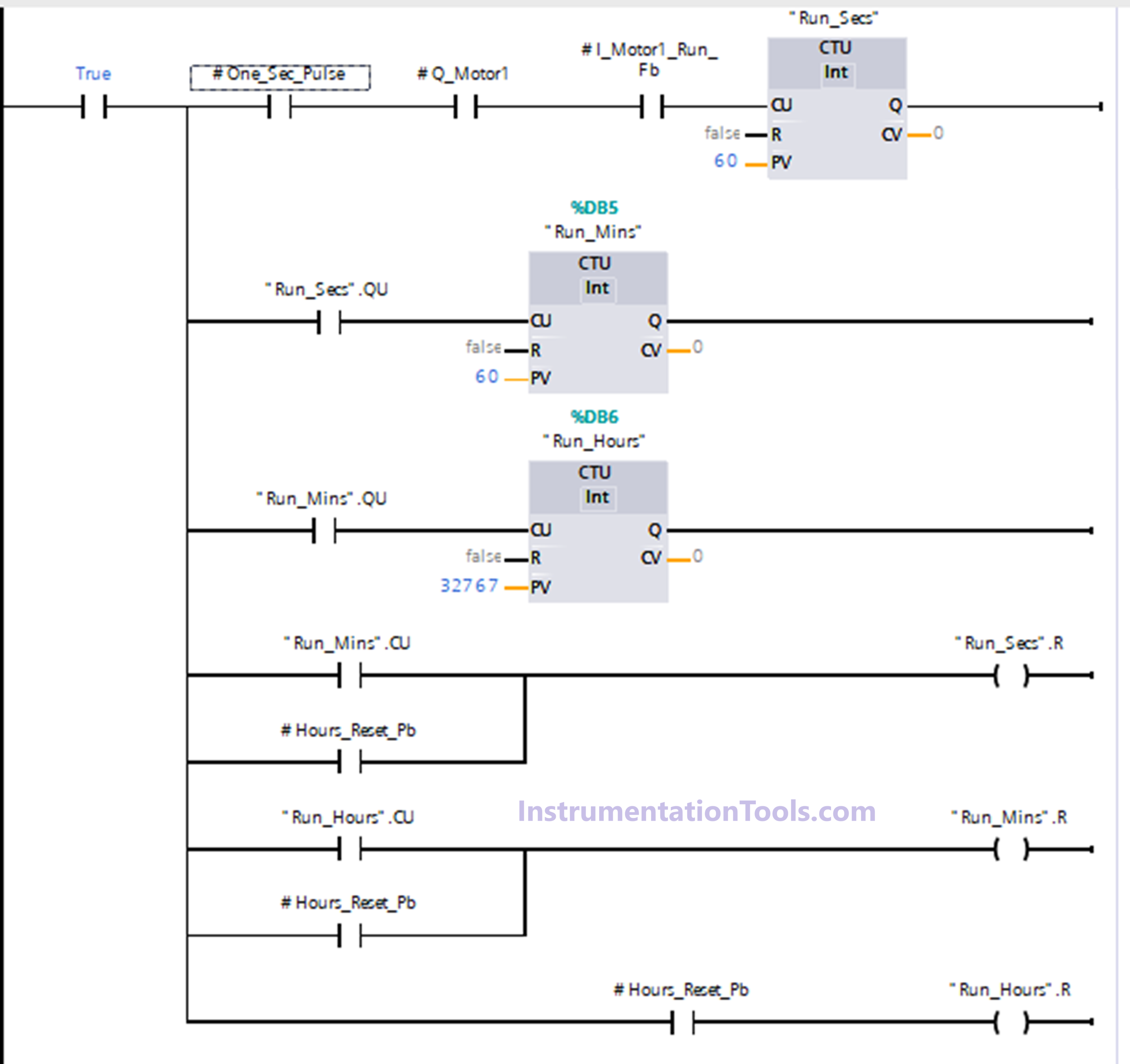
In the ninth image, we will write the PLC logic for showing the total running hours. This step is important for maintenance purposes. When the PLC output of the motor is on and the run feedback input is also on, then only the counter will start counting.
First, we increment the counter in seconds, then the seconds counter done bit will increment the minutes counter, and then the minutes counter done bit will increment the hours counter.
Also, we reset the seconds counter when the minute counter is incremented or the reset button is pressed; we reset the minutes counter when the hour counter is incremented or the reset button is pressed and we reset the hours counter when the reset button is pressed.
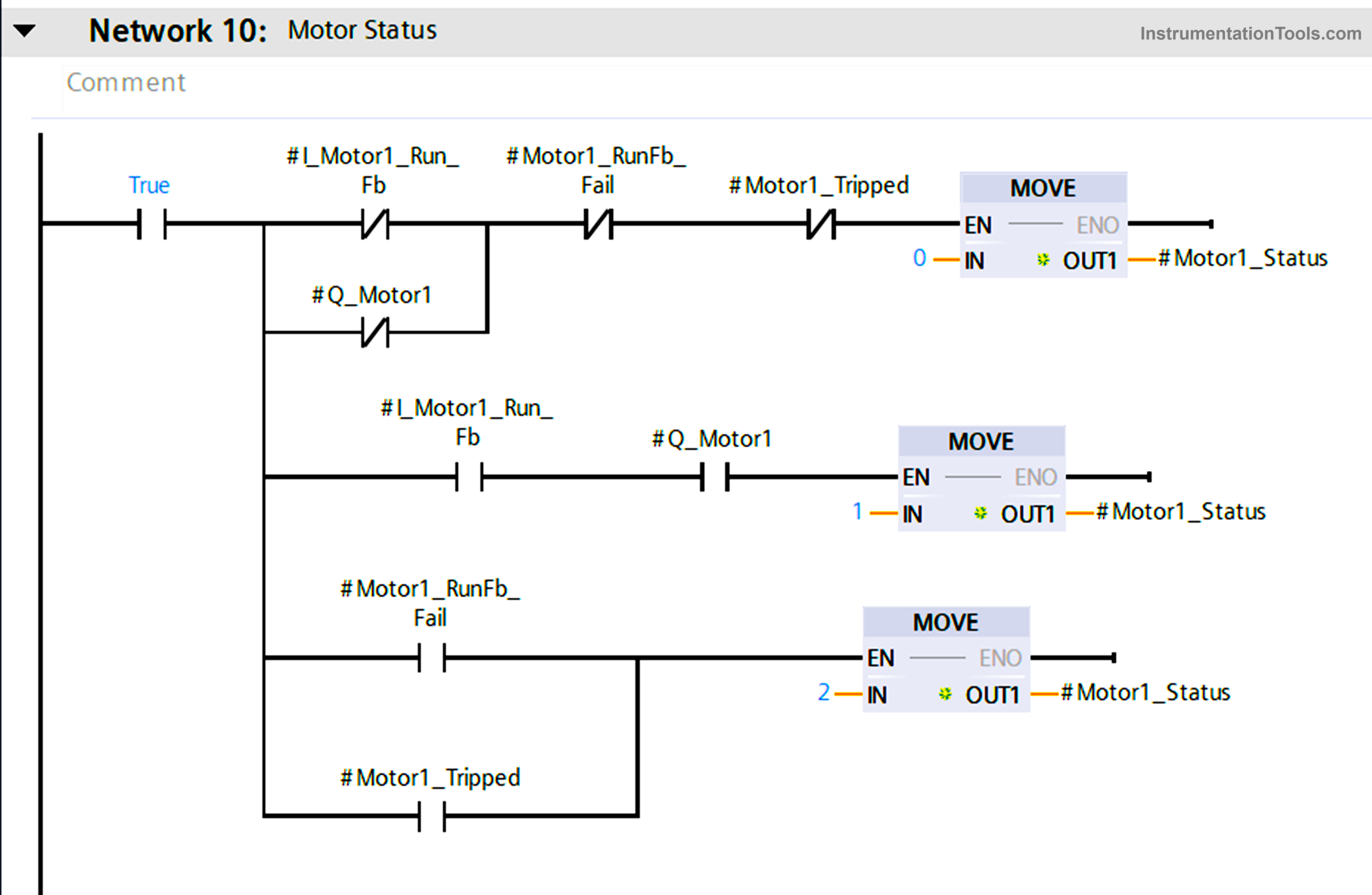
Lastly, we move the integer values in a word, depicting motor status. This is useful for graphical indication or changing the motor color in HMI / SCADA.
All this logic ensures a very safe and reliable operation of a motor through the PLC program. In this way, we saw a PLC program for motor control using the TIA Portal.
Read Next:
- Structured Text PLC Logic for Motor Interlock
- PLC Program for Water Level Control Logic
- Car Wash Program Functional Block Diagram
- Siemens VFD Configure TIA Portal Start drive
- Configure PID Controller in Schneider PLC


Can I do this example on S7 300