Inst ToolsInst ToolsInst Tools
  • Courses
  • Automation
    • PLC
    • Control System
    • Safety System
    • Communication
    • Fire & Gas System
  • Instrumentation
    • Design
    • Pressure
    • Temperature
    • Flow
    • Level
    • Vibration
    • Analyzer
    • Control Valve
    • Switch
    • Calibration
    • Erection & Commissioning
  • Interview
    • Instrumentation
    • Electrical
    • Electronics
    • Practical
  • Q&A
    • Instrumentation
    • Control System
    • Electrical
    • Electronics
    • Analog Electronics
    • Digital Electronics
    • Power Electronics
    • Microprocessor
  • Request
Search
  • Books
  • Software
  • Projects
  • Process
  • Tools
  • Basics
  • Formula
  • Power Plant
  • Root Cause Analysis
  • Electrical Basics
  • Animation
  • Standards
  • 4-20 mA Course
  • Siemens PLC Course
Reading: Functional Safety Terminology in Industrial Automation
Share
Font ResizerAa
Inst ToolsInst Tools
Font ResizerAa
  • Courses
  • Design
  • PLC
  • Interview
  • Control System
Search
  • Courses
  • Automation
    • PLC
    • Control System
    • Safety System
    • Communication
    • Fire & Gas System
  • Instrumentation
    • Design
    • Pressure
    • Temperature
    • Flow
    • Level
    • Vibration
    • Analyzer
    • Control Valve
    • Switch
    • Calibration
    • Erection & Commissioning
  • Interview
    • Instrumentation
    • Electrical
    • Electronics
    • Practical
  • Q&A
    • Instrumentation
    • Control System
    • Electrical
    • Electronics
    • Analog Electronics
    • Digital Electronics
    • Power Electronics
    • Microprocessor
  • Request
Follow US
All rights reserved. Reproduction in whole or in part without written permission is prohibited.
Inst Tools > Blog > Control Systems > Functional Safety Terminology in Industrial Automation

Functional Safety Terminology in Industrial Automation

Learn the functional safety terminology used in industrial automation. Learn fail-safe operation and reduce risks to personnel and equipment.

Last updated: September 16, 2024 2:18 pm
Viral Nagda
Control Systems
No Comments
Share
6 Min Read
SHARE

In industrial automation, there is always a safety hazard due to the use of critical machines and equipment around. The personnel working around must be felt safe and also the process must be executed smoothly. For this, it is necessary to implement certain safety conditions in a plant for fail-safe operation. This is called functional safety in easier terms.

Contents
What is functional safety?TerminologySafety Instrumented SystemSafety Integrity LevelRisk AssessmentIEC-61508Safety FunctionsSafety Circuit StructureDiagnostic Coverage

There are many terms related to functional safety which are used generally for understanding purposes. In this post, we will see some general functional safety terms related to industrial automation.

What is functional safety?

Functional safety is a theory and practice which involves understanding all the safety hazards and then checking how to solve them. This reduces the risk to the environment, personnel, and the machines around. Any untoward incident can occur if it is not resolved and predicted on time.

There are certain steps to be followed when designing a safety feature, like first analyzing the risk, then checking the issue, and then seeing how it can be resolved. When finally a functional safety system is designed, it ensures the automatic shutdown of a plant safely and properly removes all the hazards by solving them.

Functional Safety Terms in Industrial Automation

Terminology

Now, let us see some general terms related to functional safety in an industrial plant.

Safety Instrumented System

SIS means to add an extra layer of safety in a controlled automation system. This means, that if a process has two sensors for control, then a third sensor will be added as the master controller which will override the other two if it senses a fail situation.

Here, it basically deals with adding some critical master sensors and actuators for safely shutting down a process. It also involves the use of a safety PLC in place of standard PLC.

Safety Integrity Level

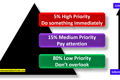
This level is used to indicate how critical safety is for a system. It is usually categorized from SIL-1 to SIL-5.

As the level increases, it shows that safety requirements to increase. For that, certain design conditions come as to what an instrument should be, how many loops can be created for safety, how many backup instruments will be present, and all.

Risk Assessment

As the name implies, risk assessment deals with analyzing the risks involved in operating a plant. Accordingly, the failure conditions will be determined, its consequences will be raised and then, how it needs to be solved will be studied. If this factor is high, then safety standards too must be maintained accordingly.

IEC-61508

IEC 61508 is an international standard that an automation system implementer must follow for fail-safe plant conditions. IEC 61508 has its own set of rules and framework that deals with safety-related operations, determining potential hazards, and removing them before they can affect a system. It has many parts and guidelines in it for helping the engineers design a system for safe operation.

Safety Functions

Safety functions consist of various processes like the use of safety drives, safety remote IO’s, safety networks, and use of features in a drive like safe torque off (STO), safe stop-1, and safe operating stop (SOS).

Safety functions also involve the use of specially designed safety devices like safety mats, safety switches, and safety power switching devices. All these generally make a part of a safety function that can be customized as per requirement.

Safety Circuit Structure

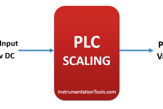
A safety circuit structure is used to design a system as to how the instruments or sensors will be configured. This means a normal system will have only one sensor for one PLC input.

But here, you can design circuits where you will have 2 sensors connected parallelly for a single PLC input, or where one field sensor will be distributed to two PLC inputs. This type of example here is called 1oo2 architecture.

Similarly, you can customize as per your design and the motive here is to create a redundancy for the field sensors and devices.

Diagnostic Coverage

For making a safe system, intense monitoring is required and diagnostic coverage involves what type of signals can be taken from an instrument, how many states can be designed in a controller program for alarm conditions, or how visually you design a SCADA screen for showing diagnostics.

A great diagnostic coverage with no use of unwanted signals can create a great safety system as the operator gets to reach out to problems easily.

In this way, we saw some general and most used terms related to functional safety in industrial automation.

Read Next:

  • Safety Instrumented System book
  • SIS Component Selection Theory
  • What is a Process Override Switch (POS)?
  • Emergency Shutdown Button Installation
  • High Integrity Pressure Protection Systems
Don't Miss Our Updates
Be the first to get exclusive content straight to your email.
We promise not to spam you. You can unsubscribe at any time.
Invalid email address
You've successfully subscribed !

Continue Reading

Tips for Reducing the Noise Signals
Proportional Controller Principle
Feedforward Vs Feedback Control
PID Controller Theory
What is ERP in Industrial Automation? – Enterprise Resource Planning
What is a Floating License? – Automation Software Systems
Share This Article
Facebook Whatsapp Whatsapp LinkedIn Copy Link
Share
Leave a Comment

Leave a Reply Cancel reply

Your email address will not be published. Required fields are marked *

Stay Connected

128.3kFollowersLike
69.1kFollowersFollow
210kSubscribersSubscribe
38kFollowersFollow

Categories

Explore More

Network Switch Requirement in SCADA and DCS Architecture
4-wire Passive versus Active Transmitters
How to Avoid Bad Grounds ?
Modbus Function Codes and Addresses
Direct Digital Control (DDC) Systems
What is a Annunciator Panel?
Node-RED in PLC Industrial Automation
Process Control Instrumentation Glossary

Keep Learning

Understanding-a-Process-Control-Loop

Understanding a Process Control Loop

Cable Glands

Using of MCT instead of Cable Glands on the Cabinets

Heuristic PID Tuning Procedure

Heuristic PID Tuning Procedure

Instrumentation Engineer in Process Plant Project

Instrumentation Engineer in Process Plant Project

Anti-static Wrist Straps

Anti-static Wrist Straps in Industrial Automation

Control Panels Material Take-Off (MTO)

Control Panels Material Take-Off (MTO) – Engineering Project

What is Timeout in Communication Protocols

What is Timeout in Communication Protocols?

Cascade Control System

Cascade Control

Learn More

PLC Program for Control Valve Scaling

PLC Program for Control Valve Scaling

Level Sensors MCQ

Level Sensors MCQ – Industrial Instrumentation

Why rating of Synchronous Generators and Alternators in MVA or KVA

Things to Know When Measuring Voltage

Things to Know When Measuring Voltage

Allen-Bradley VFD

AC Motor Speed Control

Why 4-20 mA Current Signal is used instead of Voltage Signal

Why 4-20 mA Current Signal is used instead of Voltage Signal?

Difference between Transparent Level Gauge and Reflex Level Gauge

Difference between Transparent Level Gauge and Reflex Level Gauge

Electrical Machines Questions and Answers

Synchronous Motor Phasor Diagram Questions

Menu

  • About
  • Privacy Policy
  • Copyright

Quick Links

  • Learn PLC
  • Helping Hand
  • Part Time Job

YouTube Subscribe

Follow US
All rights reserved. Reproduction in whole or in part without written permission is prohibited.
Welcome Back!

Sign in to your account

Username or Email Address
Password

Lost your password?