This article is about controlling the double-acting pneumatic cylinder movement with a timer. In this forward actuation is started by the push button and it will automatically return to its original position after reaching the limit after some delay with the help of a timer.
Pneumatic Cylinder Movement Control
Pneumatic systems are one of the major in industrial automation currently. Pneumatic systems are used in sectors like manufacturing, processing, and even in the medical field for their availability, accuracy, and safe nature.
With the help of a pneumatic system, we are controlling the actuator by delaying its return motion. This can be applied in the applications like pressing, shearing, bending, etc.
Components
- Double acting cylinder
- 3/2 Directional control valve with push button
- 5/2 Directional control valve with pilot actuated
- Air service unit
- Compressor
- 3/2 Directional Control Valve – Roller actuated:
- On delay Timer – Pneumatic
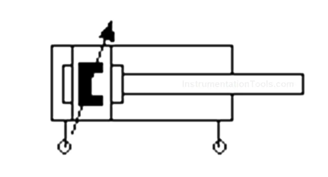
Double Acting Cylinder
A double-acting cylinder is majorly used in industrial applications because of its smooth movement and easy control. We have two passages for two sides’ actuations both forward and reverse. The name double acting indicates double side movement.
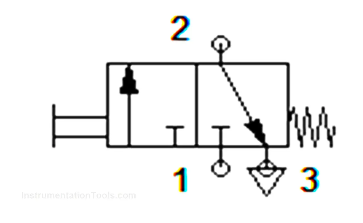
3/2 Directional Control valve with Push Button
This directional control valve is used to control the movement of the medium with the help of a push button. It contains 3 positions and 2 ports that control and move the actuators for the desired action.
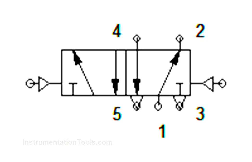
5/2 Directional control with pilot actuated
This directional control valve is used to control the flow with the signal from the medium either electrical, hydraulic, or pneumatic. In this, we used a Pneumatic actuated pilot valve for controlling the output. It consists of 5 positions and 2 ports for the movement with both sides of the pilot actuation.
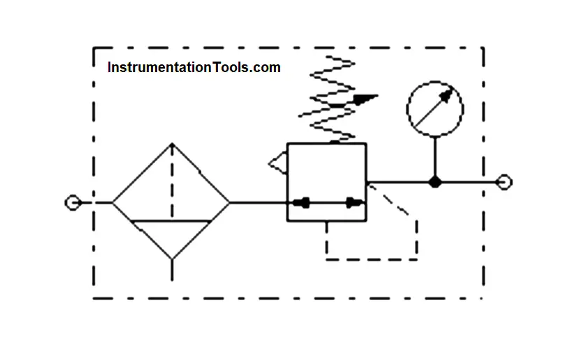
Air service unit
The air service unit is the supply and purifying component of the pneumatic system because it has a filter, regulator & lubricator in it.
Each of these will be used for different purposes like filters remove the dust contaminant of the air and send the uncontaminated supply to the system whereas a regulator is used for regulating the air supply to the desired level for the pneumatic system for the effective use and lubricator is used for giving lubrication to the system because it has so many moving components. Every pneumatic system needs to use an air service unit for efficient working
Compressor
The compressor is used to give input air supply to the system. This compressor generates the compressed air and creates the high-pressure medium that used for the movement in the system. It takes air from the atmosphere and increase its pressure for working & it also stores energy for future use.
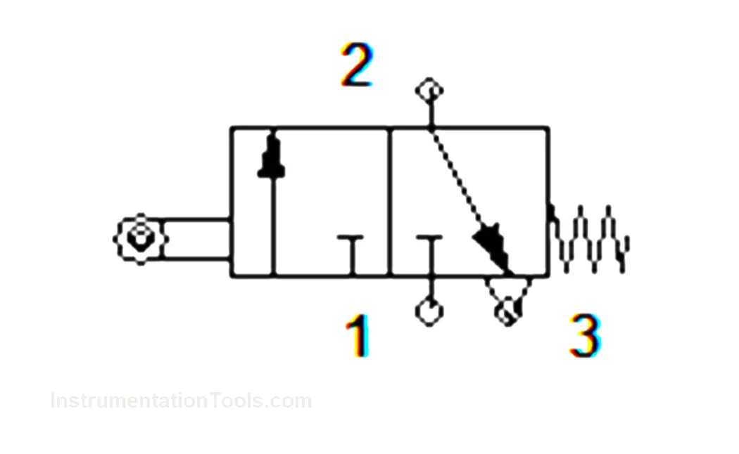
3/2 Directional Control Valve – Roller actuated
Roller actuated – 3/2 Directional Control Valve is a component used to sense the end position of the operation. This roller-actuated 3/2 directional valve is as same as limit switch in electrical.
The roller actuation controls the valve for definite control in the system. Since it is a 3/2 Direction control valve it has 3 positions and 2 ports.
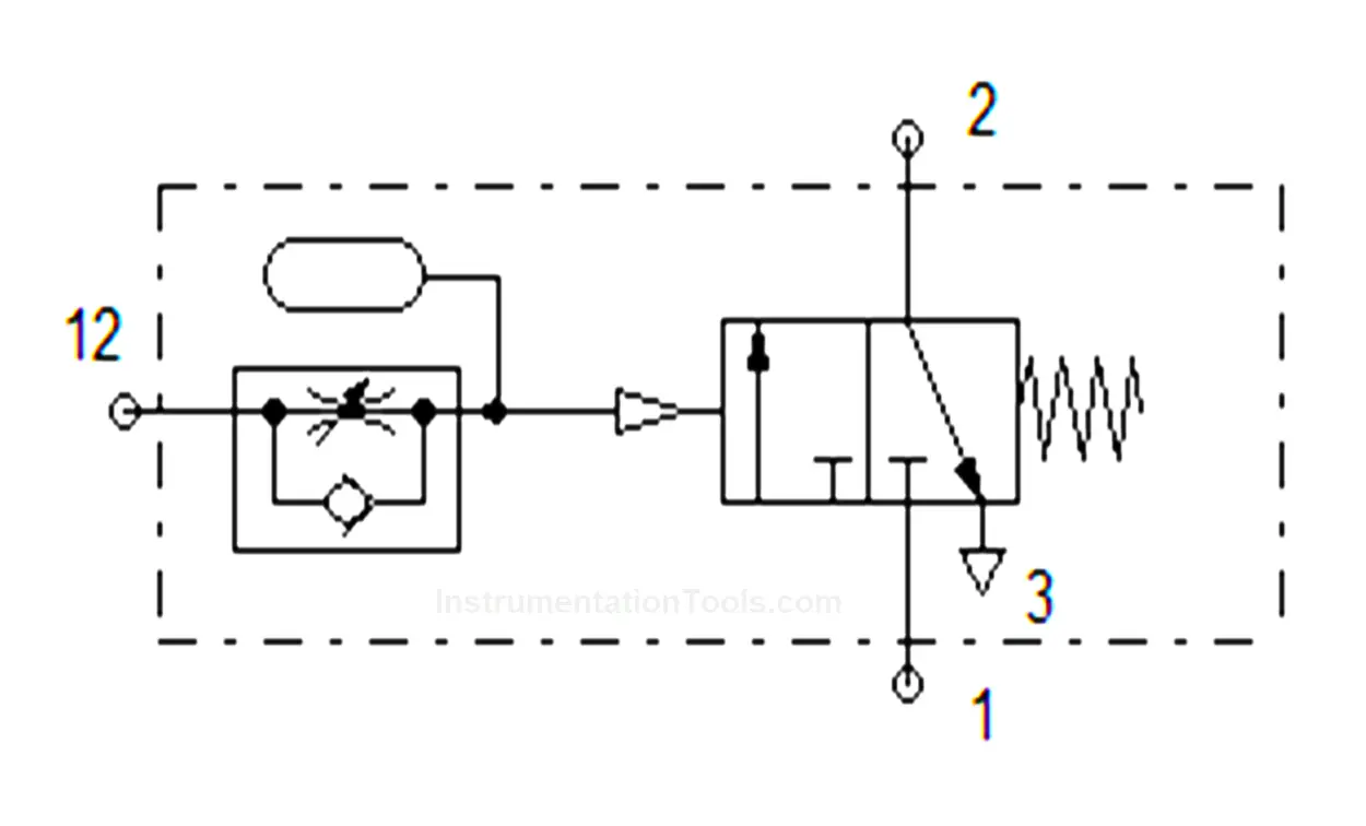
On delay Timer- Pneumatic
A pneumatic on-delay timer is like an electrical on-delay timer, which delays the process by its control signal. It has an accumulator inside it stores the medium and releases it later for the function. There is a knob in the timer, the knob controls the accumulator which defines the delay time.
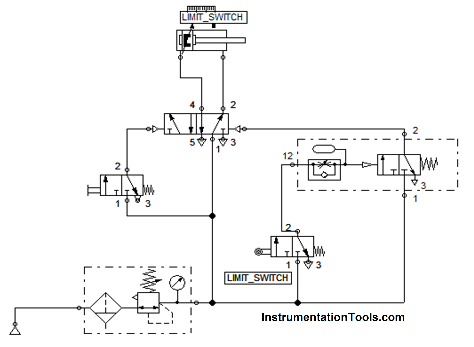
Circuit
Working
The compressed air supply is produced by the compressor & given to the Air supply unit which filters, regulates, and gives lubrication to the compressed air for the operation.
The output of the air service unit is connected to the 3/2 DCV push button which starts the controls of the whole operation.
By pressing the push button, the compressed air was moved to the 5/2 pilot valve signal and the received signal moves the cylinder forward.
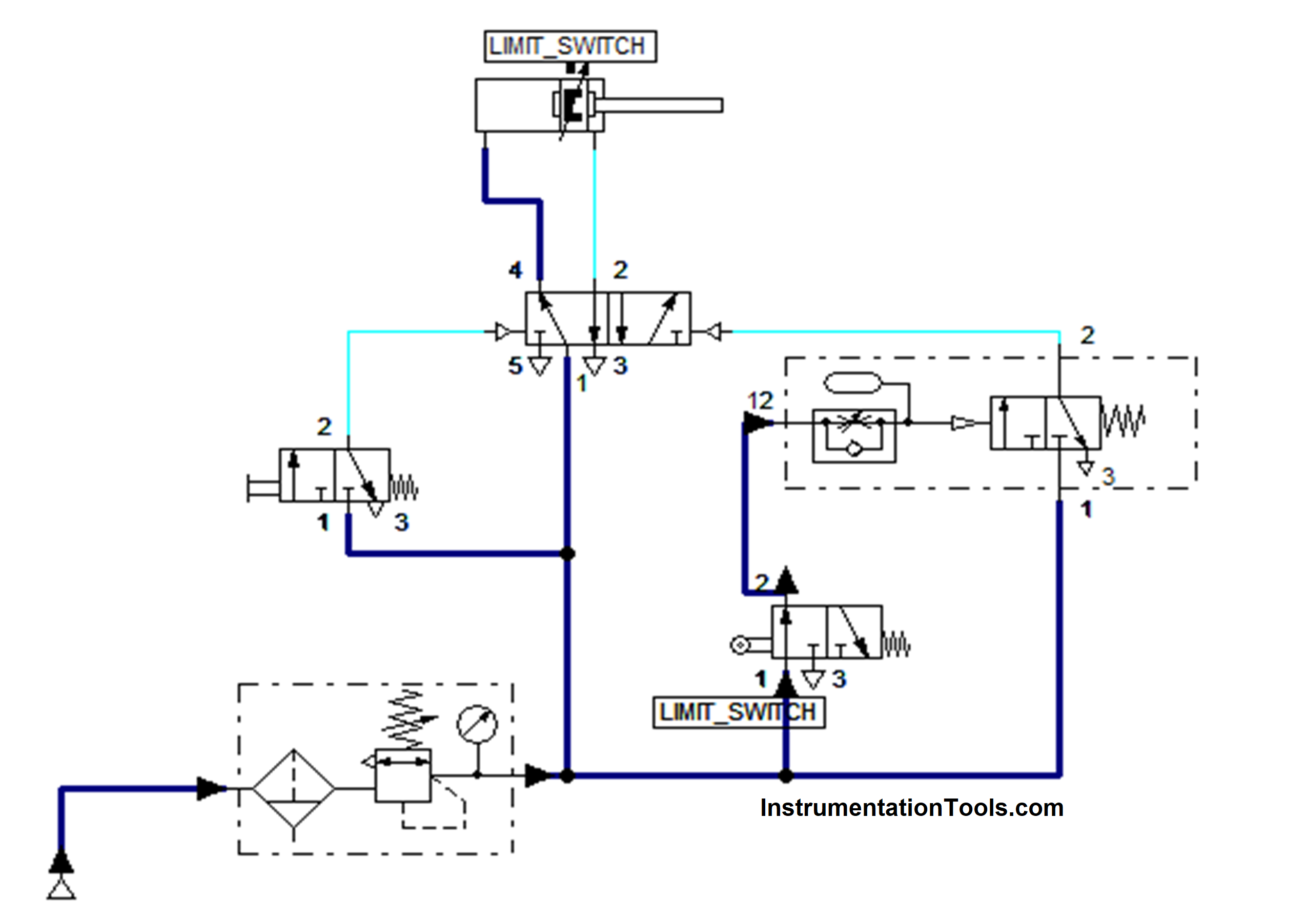
Once the cylinder moves forward, it automatically touches the roller valve and it will produce the signal. The produced signal was passed to the timer which creates the delay.
Then the output of the timer was connected to the other side of the signal of the 5/2 pilot valve which moved the cylinder to backwards. Thus one stroke was completed by creating the delay in the reverse direction.
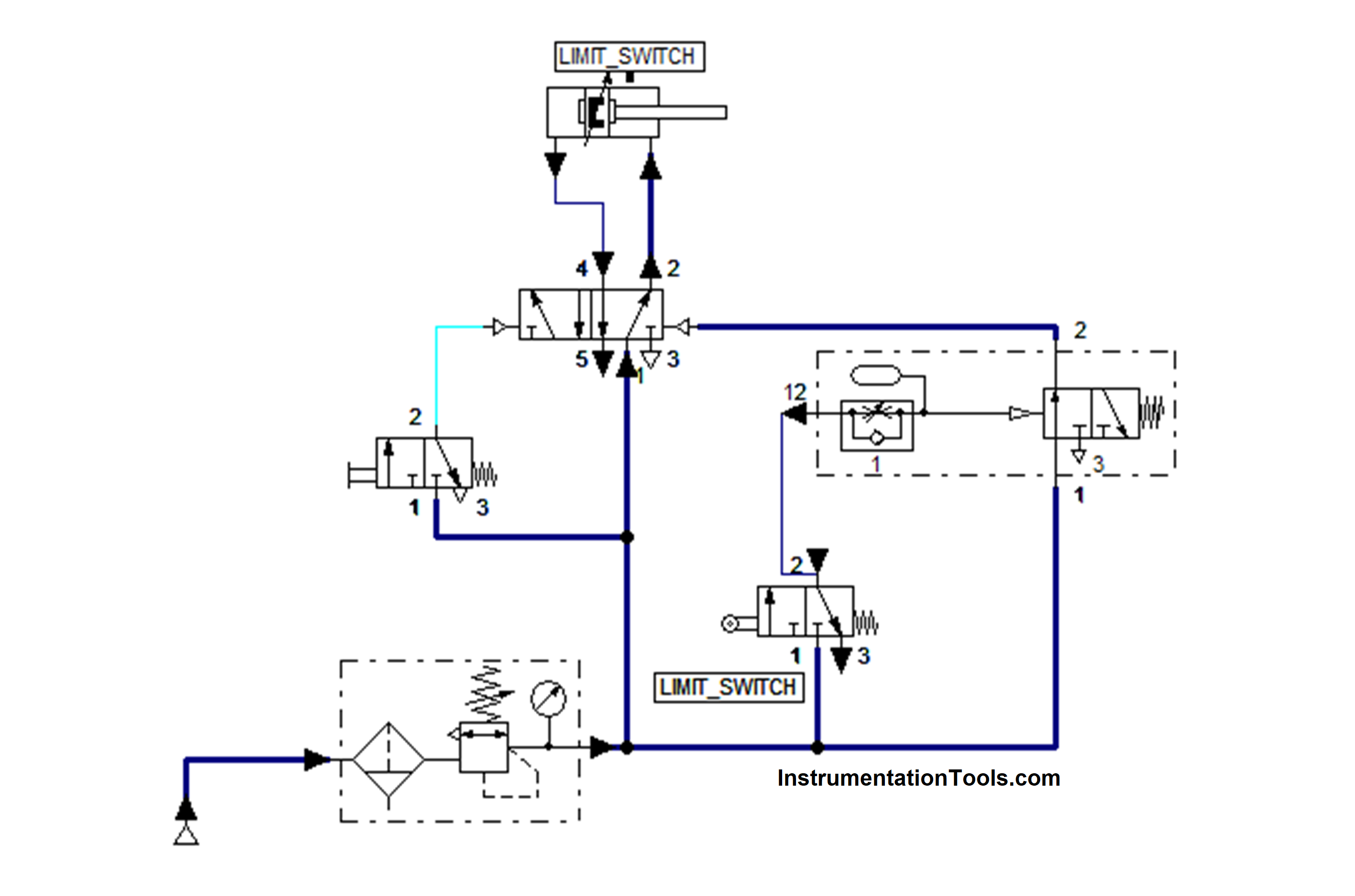
Then the process was continued by pressing the push button again. This type of circuit was used in industrial pressing, shearing, and bending operations.
Read Next:
- Pneumatic Book Download Free
- Pneumatic Valves and Cylinders Sizing
- Control of Pneumatic Cylinder and Motor
- Free Cylinder Valve Sizing Calculator
- Sequential PLC Program Pneumatic Valve


Where can I find the pneumatic symbols if you can help me, thank you