In this article, you will learn the pump and mixer operations example with a PLC timer-based control application program.
Note: This PLC exercise can be used to learn the ladder logic programming.
Pump and Mixer Operations Example
Problem Statement:
Design a PLC ladder logic for the following application.
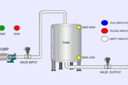
We are using one toggle switch to control Pump 1, Valve 1, Valve 2, Mixer, and Pump 2.
The pump should run for 30 seconds to fill a tank, and then Valve 1 and Valve 2 will Open for 2 seconds each one after the other. Then the Mixer should operate for 30 seconds and finally, the Pump should drain the tank for 30 seconds.
PLC Timer-Based Control Program
This PLC video explains the pumping and mixing program in full detail.
Inputs and Outputs
Digital Inputs:
Start Button: I0.0
Digital Outputs:
Pump: Q0.0
Valve 1: Q0.1
Valve 2: Q0.2
Mixer: Q0.3
Pump 2:Q0.4
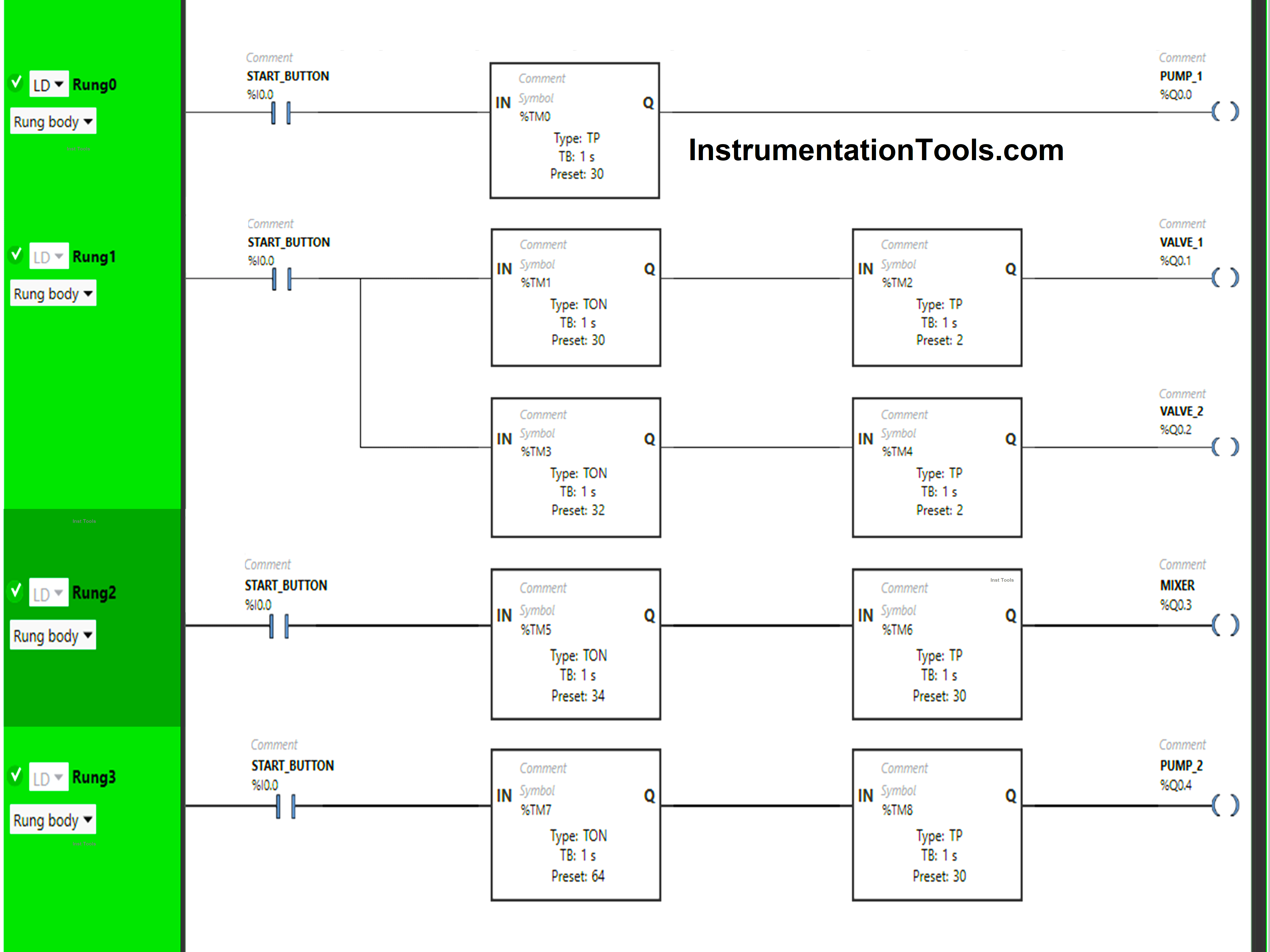
Ladder Diagram
Program Description
We have used Normally Open Contact for the Start Button (I0.0).
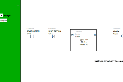
In Rung 0:
- Normally Open Contact is used for the Start Button (I0.0) to Turn ON the output Pump 1 (Q0.0).
- Timer type TP is used to Turn ON the output Pump 1 (Q0.0) for a limited time.
In Rung 1:
- Normally Open Contact is used for the Start Button (I0.0) to Turn ON the outputs Valve 1 (Q0.1) and Valve 2 (Q0.2).
- Timer type TON is used to delay the turning ON time of the output Valve 1 (Q0.1) for some time.
- Timer type TP is used to Turn ON the output Valve 1 (Q0.1) for a limited time.
- Timer type TON is used to delay the turning ON time of the output Valve 2 (Q0.2) for some time.
- Timer type TP is used to Turn ON the output Valve 2 (Q0.2) for a limited time.
In Rung 2:
- Normally Open Contact is used for the Start Button (I0.0) to Turn ON the output Mixer (Q0.3).
- Timer type TON is used to delay the turning ON time of the output Mixer (Q0.3) for some time.
- Timer type TP is used to Turn ON the output Mixer (Q0.3) for a limited time.
In Rung 3:
- Normally Open Contact is used for the Start Button (I0.0) to Turn ON the output Pump 2 (Q0.4).
- Timer type TON is used to delay the turning ON time of the output Pump 2 (Q0.4) for some time.
- Timer type TP is used to Turn ON the output Pump 2 (Q0.4) for a limited time.
Simulation Results
Let’s check the program result with the simulation. We show the partial logic instead of the complete PLC code.
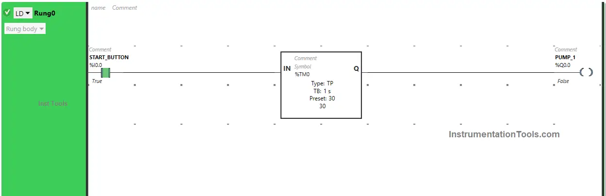
Rung 0:
When the Start Button (I0.0) is turned ON, the output Pump 1 (Q0.0) turns ON (Pump starts filling the tank) but for a limited time as Timer Function type TP is used to turn ON the Output Pump 1 (Q0.0) or fill the tank for limited time.
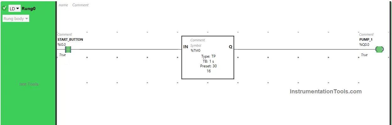
The time is set to 30 seconds.
So after 30 seconds, the output Pump 1 (Q0.0) will turn OFF or after 30 seconds, the Pump stops filling the tank.
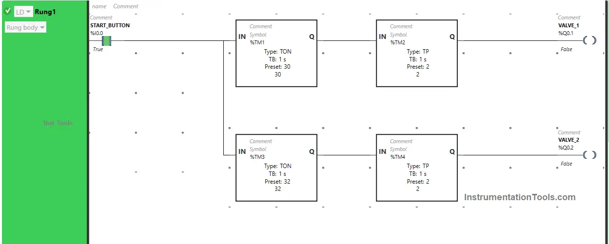
Rung 1:
When the Start Button (I0.0) is turned ON, the output Valve 1 (Q0.1) will turn ON after 30 seconds or Valve 1 will Open after 30 seconds (i.e immediately after the output Pump 1(Q0.0) turns OFF or after filling of the tank is finished) because Timer Function Block TON is used to delay the turning ON time of the output Valve 1 (Q0.1).
The time is set to 30 seconds.
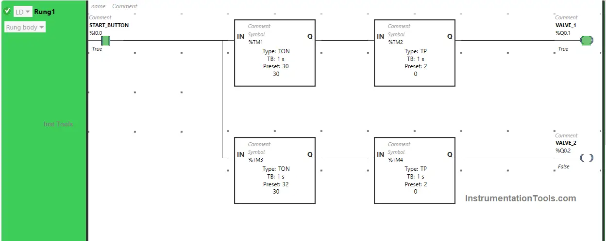
After 30 seconds, the output Valve 1 (Q0.1) will turn ON or after 30 seconds Valve 1 will open but for a limited time as Timer Function Block type TP is used to turn ON the output Valve 1 (Q0.1) for a limited time. The time is set to 2 seconds.
After 2 seconds, the output Valve 1 (Q0.1) turns OFF, or after 2 seconds Valve 1 closes.
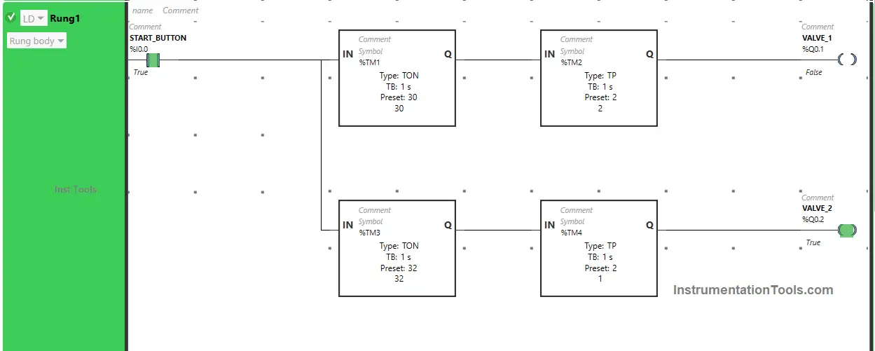
Also, when Start Button (I0.0) is turned ON, the output Valve 2 (Q0.2) will turn ON after 32 seconds or Valve 2 will Open after 32 seconds (i.e immediately after the output Valve 1(Q0.1) turns OFF or after Valve 1 Closes) because Timer Function Block TON is used to delay the turning ON time of the output Valve 2 (Q0.2).
The time is set to 32 seconds.
So after 32 seconds, the output Valve 2 (Q0.2) will turn ON or after 32 seconds Valve 2 will open but for a limited time as Timer Function Block type TP is used to turn ON the output Valve 2 (Q0.2) for a limited time.
The time is set to 2 seconds. So after 2 seconds, the output Valve 2 (Q0.2) turns OFF, or after 2 seconds Valve 2 closes.
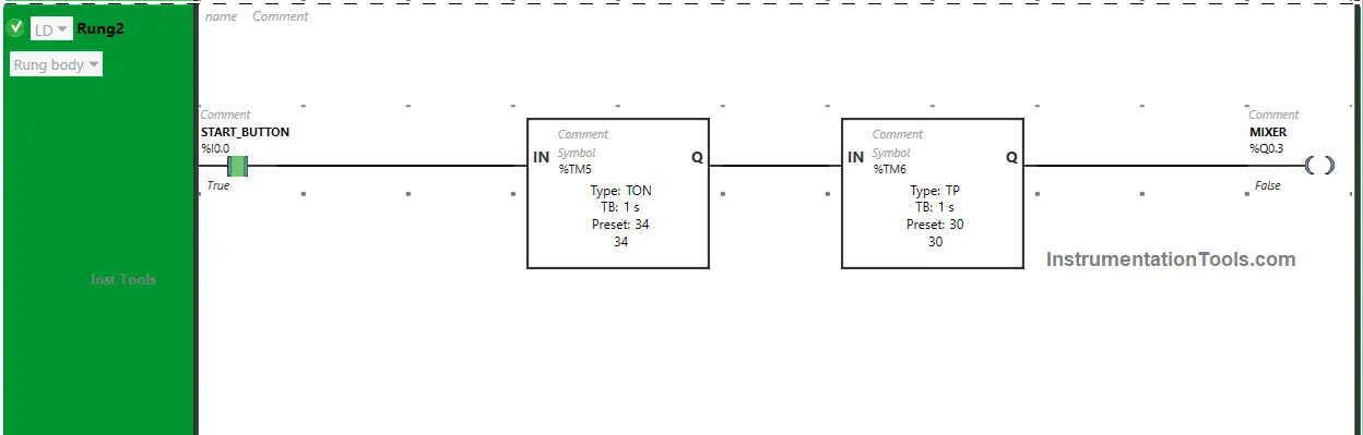
Rung 2:
When the Start Button (I0.0) is turned ON, the output Mixer (Q0.3) will turn ON after 34 seconds, or after 34 seconds Mixer starts (i.e immediately after the output Valve 2 (Q0.2) turns OFF or after Valve 2 closes) because Timer Function Block TON is used to delay the turning ON time of the output Mixer (Q0.3). The time is set to 34 seconds.
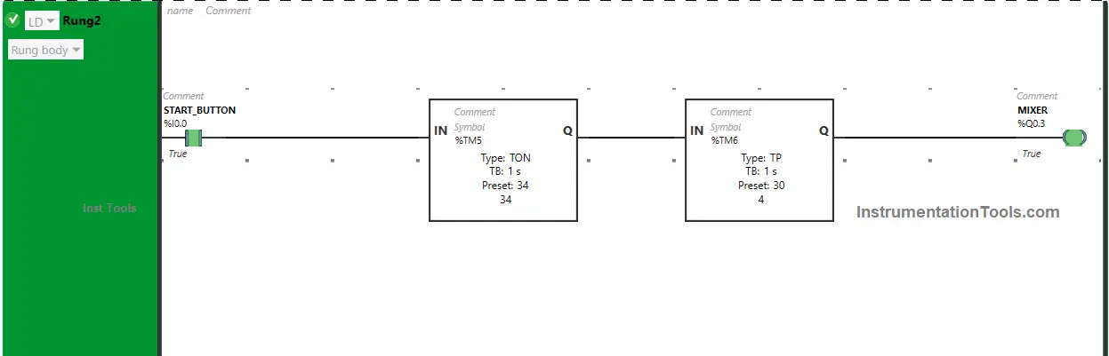
After 34 seconds, the output Mixer (Q0.3) will turn ON, or after 34 seconds Mixer starts but for a limited time as Timer Function Block type TP is used to turn ON the output Mixer (Q0.3) for a limited time. The time is set to 30 seconds. So after 30 seconds, the output Mixer (Q0.3) turns OFF or after 30 seconds Mixer stops.
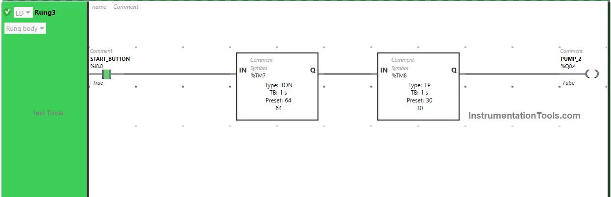
Rung 3:
When the Start Button (I0.0) is turned ON, the output Pump 2 (Q0.4) will turn ON after 64 seconds, or after 64 seconds Pump 2 starts draining the tank (i.e immediately after the output Mixer (Q0.3) turns OFF or after Mixer stops) because Timer Function Block TON is used to delay the turning ON time of the output Pump 2 (Q0.4).
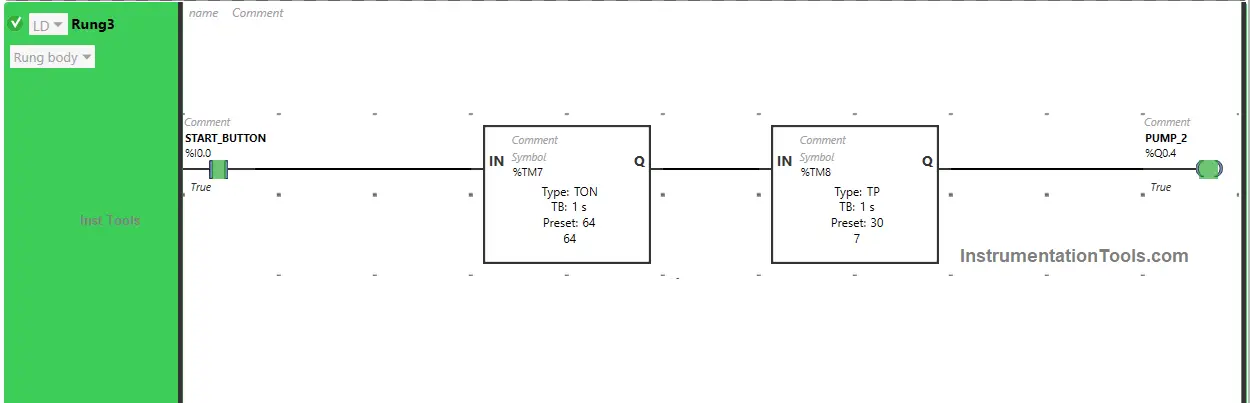
The time is set to 64 seconds. So after 64 seconds, the output Pump 2 (Q0.4) will turn ON or after 44 seconds Pump 2 starts draining the tank but for a limited time as Timer Function Block type TP is used to turn ON the output Pump 2 (Q0.4) for a limited time.
The time is set to 30 seconds. So after 30 seconds, the output Pump 2 (Q0.4) turns OFF or after 30 seconds Pump 2 stops draining the tank.
If you liked this article, please subscribe to our YouTube Channel for PLC and SCADA video tutorials.
You can also follow us on Facebook and Twitter to receive daily updates.
Read Next:
- Connecting Faceplate to PLC Project Tutorial
- Batch Mixing with PLC Ladder Logic Program
- PLC Example Program using LogixPro Simulator
- PLC Program Sorting Boxes by Height Ladder Logic
- PLC Programming Example for a Batch Process