In Playground Swing Logic, a timer should count down from 30 seconds when a child starts Swinging. An Alarm activates after time is up.
Note: This PLC program was created for the persons to learn the PLC basics.
Playground Swing Logic
Problem Statement
Design a PLC ladder logic for the following application.
We are using one toggle switch and one Push Button to control the Alarm.
When a child starts Swinging, a timer should count down from 30 seconds. An Alarm should sound when the time is up.
A Reset Button will start the countdown again.
PLC Basics for Students
Instrumentation Tools provides the PLC basics with simple problems and solutions for students.
This video explains swing example programming using ladder logic.
Inputs and Outputs
Digital Inputs:
Start Button: I0.0
Reset Button: I0.1
Digital Outputs:
Alarm: Q0.0
Program in PLC
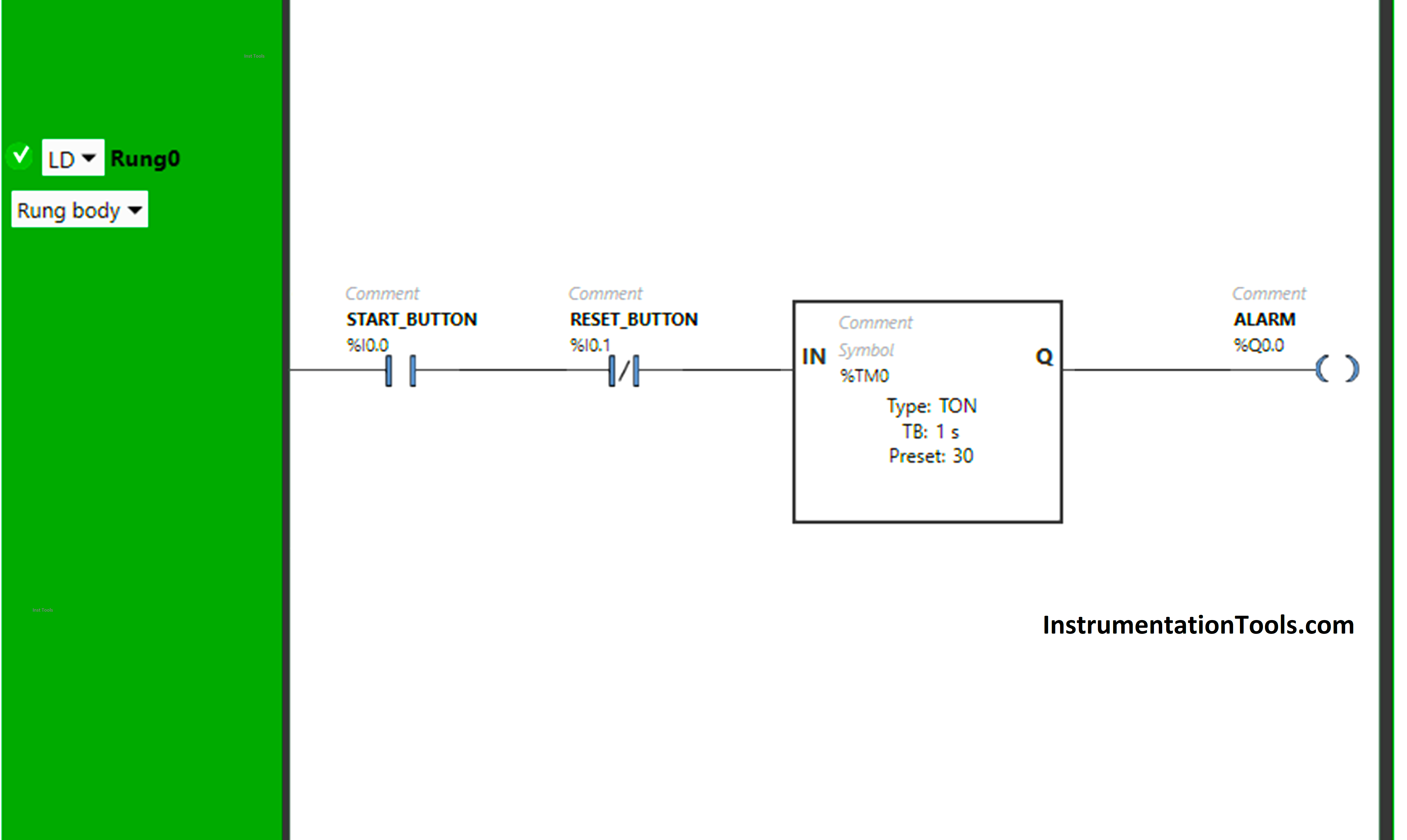
Explanation
We have used Normally Open Contact for the Start Button (I0.0).
We have used Normally Closed Contact for the Reset Button (I0.1).
In Rung 0:
- Normally Open Contact is used for the Start Button (I0.0) to Turn ON the output Alarm (Q0.0)
- Timer TON is used to delay the turning ON time of the output Alarm (Q0.0) for some time.
- Normally Closed Contact is used for Reset Button (I0.1) to turn OFF the output Alarm (Q0.0) and restart the timer.
When the Start Button (I0.0) is turned ON or (child starts swinging), the output Alarm (Q0.0) will turn ON after 30 seconds as Timer Function Block TON is used to delay the turning ON time of the output Alarm (Q0.0). The time is set to 30 seconds.
In a false state, Normally Closed Contact used for the Reset Button (I0.1) passes the signal to turn ON the output Alarm (Q0.0). After 30 seconds, the output Alarm (Q0.0) will turn ON.
When Reset Button (I0.1) is pressed and released, the output Alarm (Q0.0) will turn OFF because When the Reset Button (I0.1) is pressed, Normally Closed Contact used for Reset Button (I0.0) will be in True state and does not allow the signal to pass through it and the output Alarm (Q0.0) will turn OFF.
When the Reset Button is released (I0.1), Normally Closed Contact used for the Reset Button (I0.0) will be in a false state and allow the signal to pass through it. Then, the timer again starts in the Timer Function Block type TON. The time is set to 30 seconds. After 30 seconds, the output Alarm (Q0.0) will turn ON again.
Simulation Results
Now we simulate our PLC program and discuss the results.
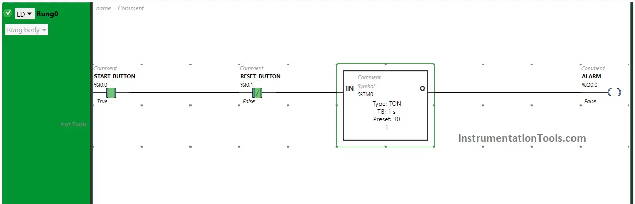
When the Start Button is turned ON (Child Starts Swinging)
When the Start Button (I0.0) is turned ON or (child starts swinging), the output Alarm (Q0.0) will turn ON after 30 seconds as Timer Function Block TON is used to delay the turning ON time of the output Alarm (Q0.0).
The time is set to 30 seconds.
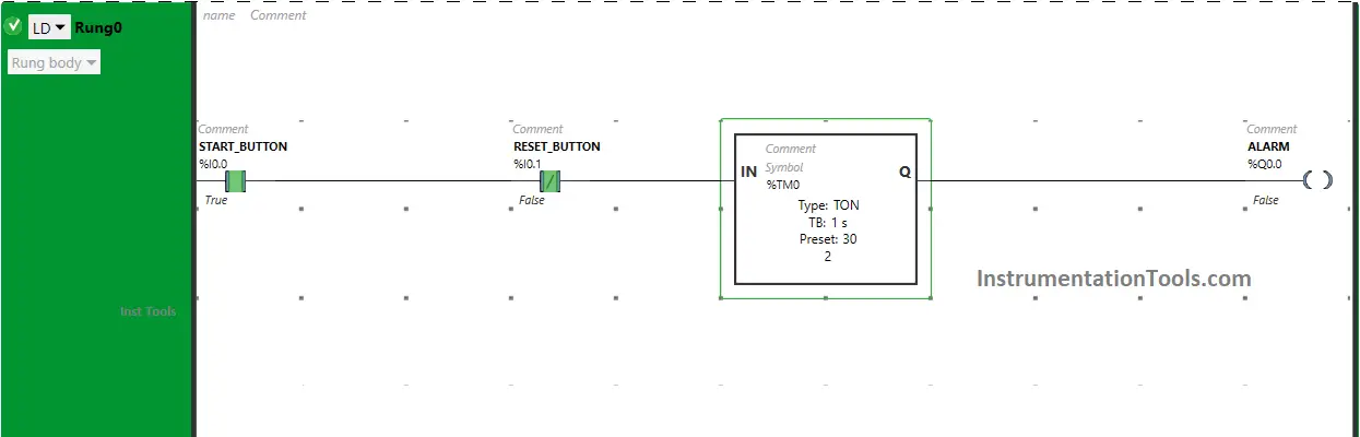
In a false state, Normally Closed Contact used for the Reset Button (I0.1) passes the signal to turn ON the output Alarm (Q0.0).
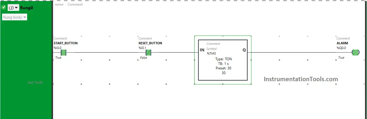
After 30 seconds, the output Alarm (Q0.0) will turn ON.

When the Reset Button is Pressed and Released
When the Reset Button (I0.1) is pressed and released, the output Alarm (Q0.0) will turn OFF because When the Reset Button (I0.1) is pressed.
Normally Closed Contact used for the Reset Button (I0.0) will be in a True state and does not allow the signal to pass through it and the output Alarm (Q0.0) will turn OFF.
When the Reset Button is released (I0.1), Normally Closed Contact used for the Reset Button (I0.0) will be in a false state and allow the signal to pass through it.
Then, the timer again starts in the Timer Function Block type TON. The time is set to 30 seconds. After 30 seconds, the output Alarm (Q0.0) will turn ON again.
If you liked this article, please subscribe to our YouTube Channel for PLC and SCADA video tutorials.
You can also follow us on Facebook and Twitter to receive daily updates.
Read Next:
- Traffic Lights PLC Program using Timers
- Heater and Cooler PLC Exercise Problem
- PLC Applications Examples of Door Lock
- Door Lock with Delay PLC Exercise Problem
- PLC Emergency Stop Example Programming


Hello sir, how do I get a PLC programmer certificate?
Join Here – https://learn.automationcommunity.com/courses/