Design a control system for automatic door lock with delay using PLC programming.
Note: This PLC program was created for the persons for learning the PLC programming with simple problems.
Door Lock with Delay
Problem Statement:
Design a PLC ladder logic for the following application.
We are using one Sensor to control the Door Lock.
The Motion Sensor detects when someone approaching the door should wait for 10 seconds and then open it. If no one is detected for 5 seconds, the door should close.
PLC Exercise Problems
This video explains the PLC programming for automatic door lock with delay logic.
Inputs & Outputs
Digital Inputs:
Sensor: I0.0
Digital Outputs:
Door Lock: Q0.0
Logic Solution
Program Explained
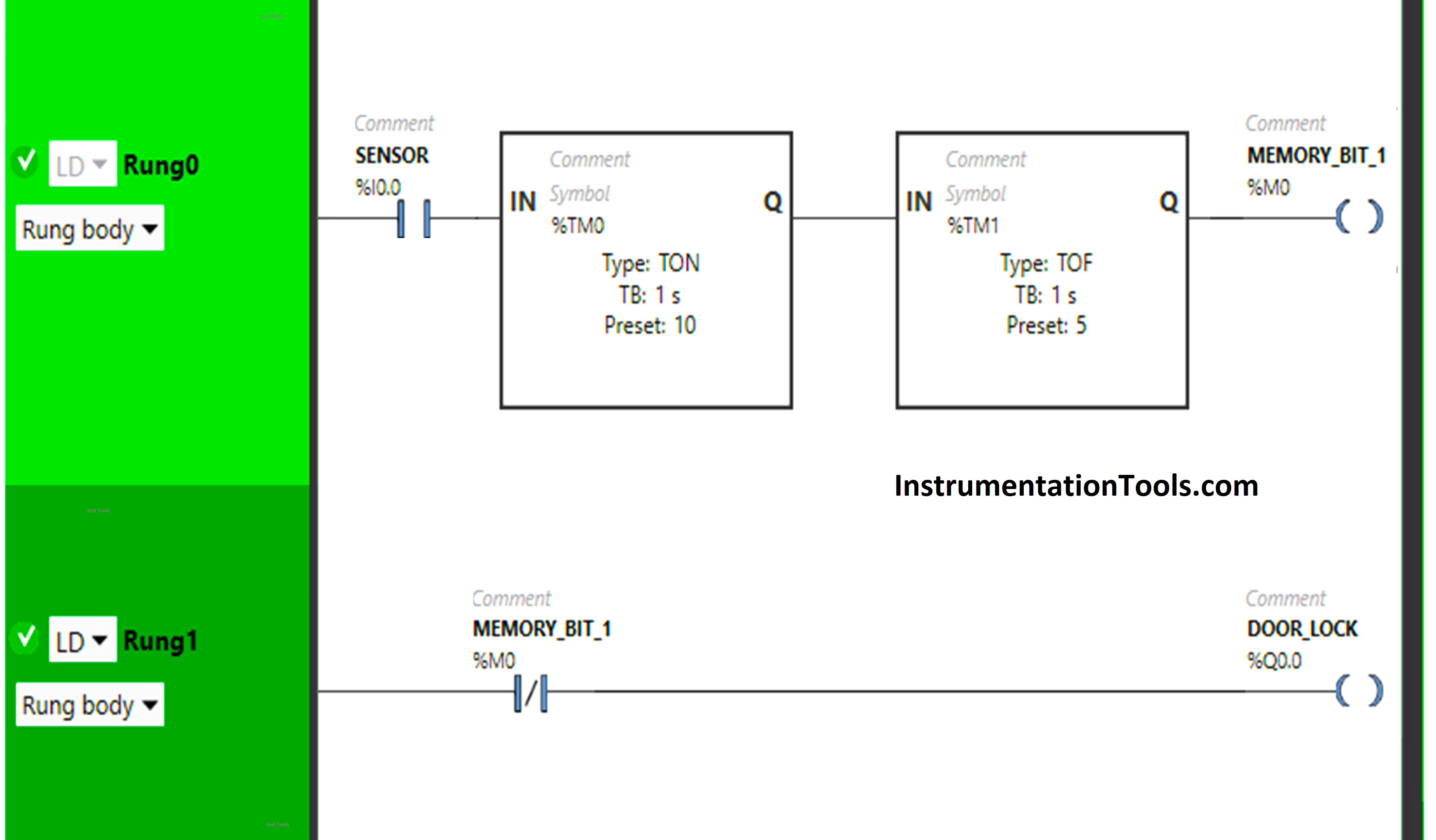
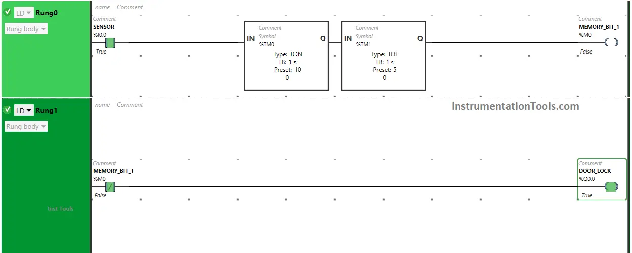
We have used Normally Open Contact for Sensor (I0.0).
We have used Normally Closed Contact for Memory Bit 1 (M0).
In Rung 0:
- Normally Open Contact is used for Sensor (I0.0) to Turn ON Memory Bit 1 (M0).
- Timer type TON is used to delay the turning ON time of Memory Bit 1 (M0) for some time.
- Timer type TOF is used to delay the turning OFF time of Memory Bit 1 (M0) for some time.
In Rung 1:
- Normally Closed Contact is used for Memory Bit 1 (M0) to Turn ON and OFF the output Door Lock (Q0.0).
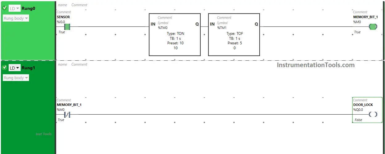
When Sensor (I0.0) gets activated or (Sensor detects someone approaching), the Memory Bit 1 (M0) will turn ON after 10 seconds as Timer Function Block TON is used to delay the turning ON time of Memory Bit 1 (M0). The time is set to 10 seconds. After 10 seconds, Memory Bit 1 (M0) will turn ON.
When Memory Bit (M0) turns ON in Rung0, Normally Closed Contact used for Memory Bit 1 (M0) in Rung1 will be True state and does not allow the signal to pass through it and the output Door Lock (Q0.0) will turn OFF or (Doors will Unlock).
When Sensor (I0.0) deactivates or ( Sensor does not detect anyone approaching), Memory Bit 1 (M0) will turn OFF after 5 seconds as Timer Function Block type TOF is used to delay the turning OFF time of Memory Bit 1 (M0). The time is set to 5 seconds.
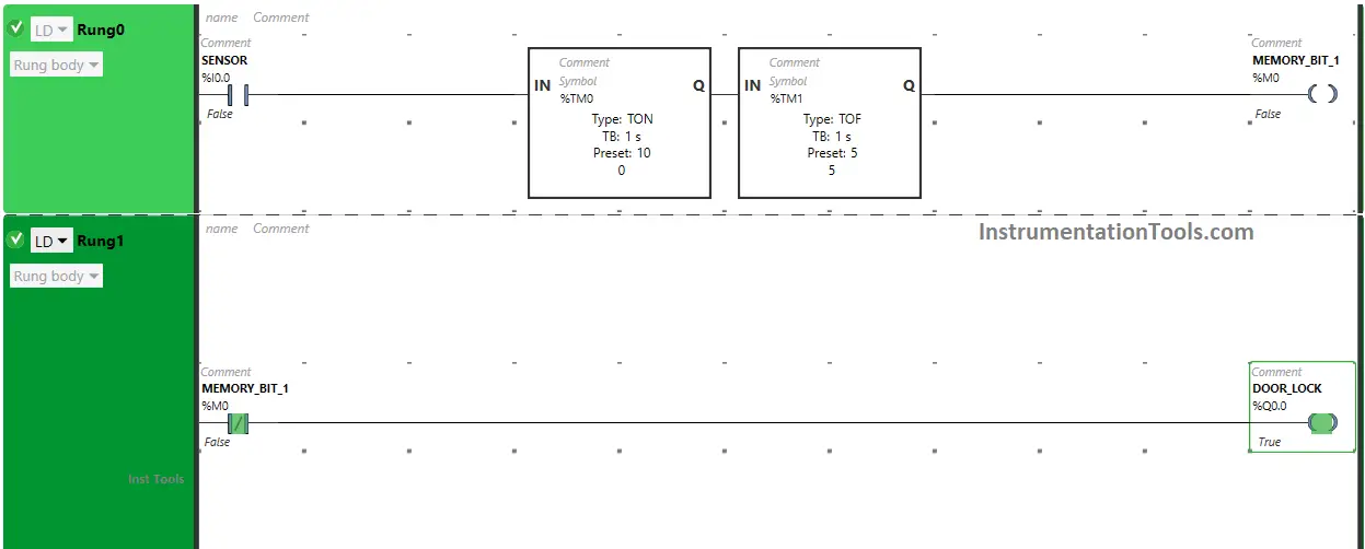
After 5 seconds, Memory Bit 1 (M0) will turn OFF. When Memory Bit 1 (M0) turns OFF in Rung0. Normally Closed Contact used for Memory Bit 1 (M0) in Rung1 will be false state and allow the signal to flow through it and the output Door Lock (Q0.0) will turn ON or (Doors will Lock).
When Sensor gets activated or Sensor detects someone approaching
When Sensor (I0.0) gets activated or (Sensor detects someone approaching), the Memory Bit 1 (M0) will turn ON after 10 seconds as Timer Function Block TON is used to delay the turning ON time of Memory Bit 1 (M0). The time is set to 10 seconds.
After 10 seconds, Memory Bit 1 (M0) will turn ON. When Memory Bit (M0) turns ON in Rung0.
Normally Closed Contact used for Memory Bit 1 (M0) in Rung1 will be True state and does not allow the signal to pass through it and the output Door Lock (Q0.0) will turn OFF or ( Doors will Unlock).
When Sensor deactivates or (When sensor does not detect anyone for 5 seconds)
When Sensor (I0.0) deactivates or ( Sensor does not detect anyone approaching), Memory Bit 1 (M0) will turn OFF after 5 seconds as Timer Function Block type TOF is used to delay the turning OFF time of Memory Bit 1 (M0). The time is set to 5 seconds.
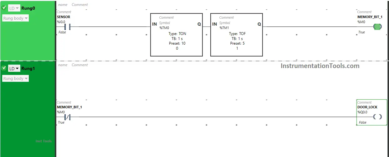
After 5 seconds, Memory Bit 1 (M0) will turn OFF. When Memory Bit 1 (M0) turns OFF in Rung0.
Normally Closed Contact used for Memory Bit 1 (M0) in Rung1 will be false state and allow the signal to flow through it and the output Door Lock (Q0.0) will turn ON or (Doors will Lock).
If you liked this article, please subscribe to our YouTube Channel for PLC and SCADA video tutorials.
You can also follow us on Facebook and Twitter to receive daily updates.
Read Next:
- PLC Example Switch Program with Timers
- Heater and Cooler PLC Exercise Problem
- Automated Garage Gate PLC Programming
- Pumping and Draining PLC Ladder Logic
- Curtain Control PLC Programming Solution