Developing PLC logic for water pumping, filtration for 30 seconds, chemical addition for 5 seconds, and then transfer the water.
We encourage students to utilize this PLC programming example for educational purposes and it provides an opportunity to learn the ladder logic through simple applications.
PLC Logic for Water Pumping
Problem Statement:
Design a PLC ladder logic for the following application.
We are using one toggle switch to control Pump 1, Filtration, Chemical, and Pump 2.
Start the Water Pump 1 to transfer the water. Then Filtration for 30 seconds, then the addition of Chemicals for 5 seconds, and then Pump 2 will be ON to transfer water into the storage tank.
PLC Training Series
This free PLC training series is designed for everyone to learn about PLC programming.
Watch this video to understand about this program.
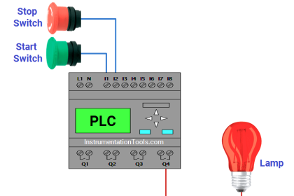
Inputs and Outputs
Digital Inputs:
Start Button: I0.0
Digital Outputs:
Pump 1: Q0.0
Filtration: Q0.1
Chemical: Q0.2
Pump 2: Q0.3
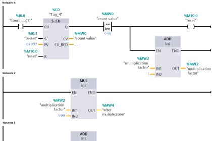
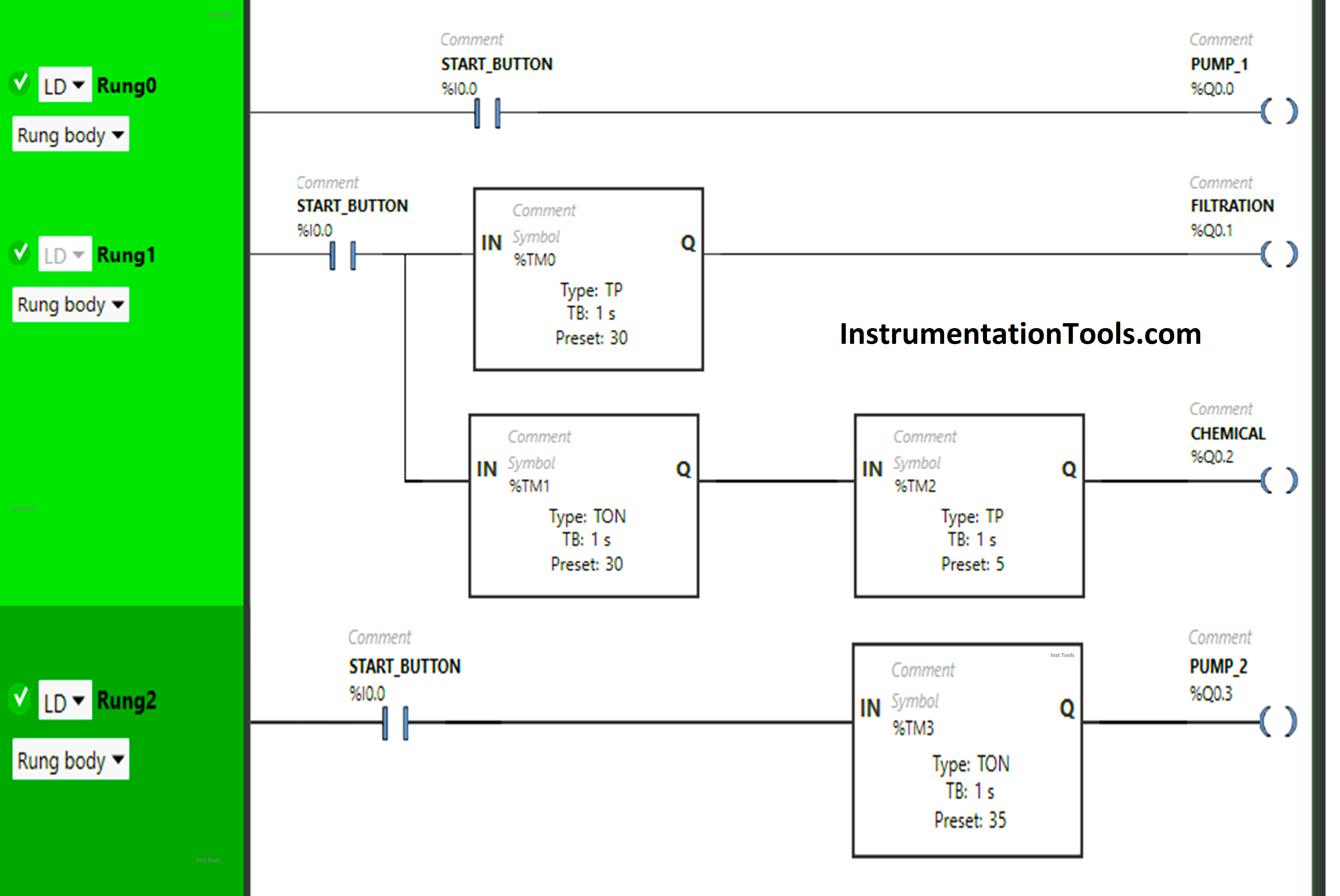
Ladder Diagram
Program Description
We have used Normally Open Contact for the Start Button (I0.0).
In Rung 0:
- Normally Open Contact is used for the Start Button (I0.0) to Turn ON the output Pump 1 (Q0.0).
In Rung 1:
- Normally Open Contact is used for the Start Button (I0.0) to Turn ON the outputs Filtration (Q0.1) and Chemical (Q0.2).
- Timer type TP is used to Turn ON the output Filtration (Q0.1) for a limited time.
- Timer type TON is used to delay the turning ON time of the output Chemical (Q0.2) for some time.
- Timer type TP is used to Turn ON the output Chemical (Q0.2) for a limited time.
In Rung 2:
- Normally Open Contact is used for the Start Button (I0.0) to Turn ON the outputs Pump 2 (Q0.3)
- Timer type TON is used to delay the turning ON time of the output Pump 2 (Q0.3) for some time.
PLC Program Result
Now we will see the PLC program result and observe the outputs.
Rung 0:
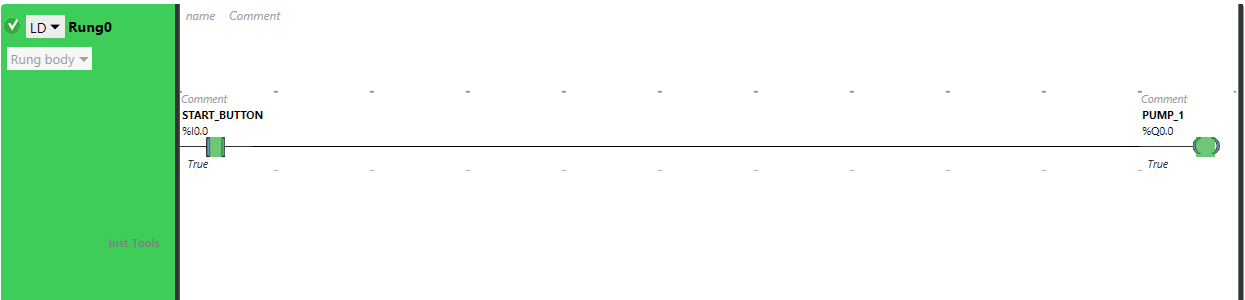
When the Start Button (I0.0) turns ON, the output Pump 1 (Q0.0) will turn ON as Normally Open Contact used for the Start Button will pass the signal to output Pump 1 (Q0.0).
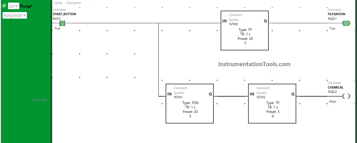
Rung 1:
When the Start Button (I0.0) is turned ON, the output Filtration (Q0.1) will turn ON for 30 seconds as Timer Function Block type TP is used to Turn ON the output Filtration (Q0.1) for a limited time. The time is set to 30 seconds.
After 30 seconds, the output Filtration (Q0.1) will turn OFF. Also, when the Start Button (I0.0) is turned ON, the output chemical will turn ON after 30 seconds, (i.e immediately when the output Filtration (Q0.1) turns OFF) as Timer Function Block TON is used to delay the turning ON time of the output Chemical (Q0.2). The time is set to 30 seconds.
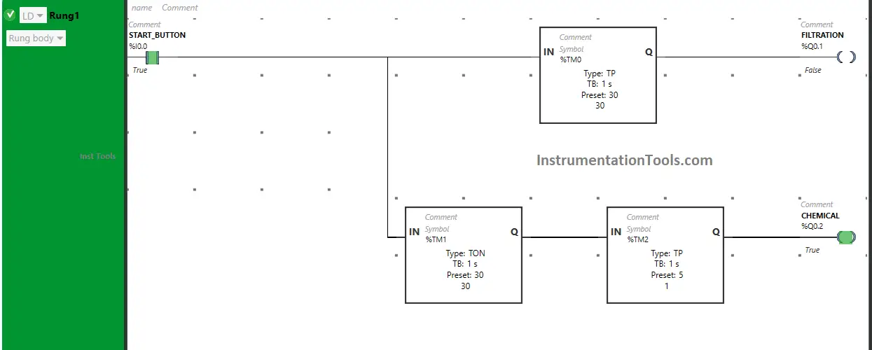
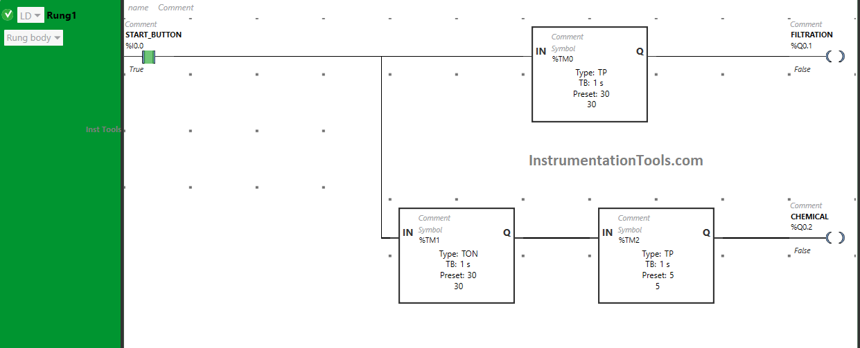
After 30 seconds, the output Chemical (Q0.2) will turn ON but only for 5 seconds as Timer Function Block type TP is used to Turn ON the output Chemical (Q0.2) for a limited time. The time is set to 5 seconds. After 5 seconds, the output Chemical (Q0.2) will turn OFF.
Rung 2:
When the Start Button (I0.0) is turned ON, the output Pump 2 (Q0.3) will turn ON after 35 seconds (i.e. immediately when the output Chemical (Q0.2) turns OFF).
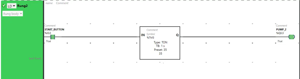
As Timer Function Block TON is used to delay the turning ON time of the output Pump 2 (Q0.3). The time is set to 35 seconds. After 35 seconds, the output Pump (Q0.3) will turn ON.
If you liked this article, please subscribe to our YouTube Channel for PLC and SCADA video tutorials.
You can also follow us on Facebook and Twitter to receive daily updates.
Read Next:
- PLC Logic for Stairway Lighting
- PLC Programming for Barrier Control
- Traffic Lights PLC Logic using Timers
- Control Spray Nozzle, Fans, Puncher
- PLC Conveyor Forward and Reverse