Inst ToolsInst ToolsInst Tools
  • Courses
  • Videos
  • Q & A
    • Interview
      • Instrumentation
      • Electronics
      • Electrical
      • Practical Questions
    • MCQ
      • Instrumentation MCQ
      • Electrical MCQ
      • Electronics MCQ
      • Control Systems MCQ
      • Analog Electronics MCQ
      • Digital Electronics MCQ
      • Power Electronics MCQ
      • Microprocessor MCQ
      • Multiple Choice Questions
  • EE
    • Electronics
      • Electronics Q & A
      • Electronic Basics
      • Electronic Devices & Circuits
      • Electronics Animation
      • Digital Electronics
    • Electrical
      • Electrical Basics
      • Electrical Q & A
      • Power Electronics
      • Electrical Machines
      • Electrical Animation
      • Power Systems
      • Switchgear & Protection
      • Transmission & Distribution
  • Measure
    • Control Valves
    • Calibration
    • Temperature
    • Pressure
    • Flow
    • Level
    • Analyzers
    • Switches
    • Vibration
    • Solenoid Valve
  • Control
    • PLC Tutorials
    • Control Systems
    • Safety Instrumented System (SIS)
    • Communication
    • Fire & Gas System
  • More
    • Design
    • Tools
    • Animation
    • Basics
    • Formulas
    • Standards
    • TextBooks
    • Common
    • Software
    • Excel Tools
    • Erection & Commissioning
    • Process Fundamentals
    • Videos
    • Books
Search
All rights reserved. Reproduction in whole or in part without written permission is prohibited.
Reading: Three Element Drum Level Control System
Share
Notification Show More
Font ResizerAa
Inst ToolsInst Tools
Font ResizerAa
  • Courses
  • PLC Tutorials
  • Control Systems
Search
  • Courses
  • Videos
  • Q & A
    • Interview
    • MCQ
  • EE
    • Electronics
    • Electrical
  • Measure
    • Control Valves
    • Calibration
    • Temperature
    • Pressure
    • Flow
    • Level
    • Analyzers
    • Switches
    • Vibration
    • Solenoid Valve
  • Control
    • PLC Tutorials
    • Control Systems
    • Safety Instrumented System (SIS)
    • Communication
    • Fire & Gas System
  • More
    • Design
    • Tools
    • Animation
    • Basics
    • Formulas
    • Standards
    • TextBooks
    • Common
    • Software
    • Excel Tools
    • Erection & Commissioning
    • Process Fundamentals
    • Videos
    • Books
Follow US
All rights reserved. Reproduction in whole or in part without written permission is prohibited.
Inst Tools > Blog > Control Systems > Three Element Drum Level Control System

Three Element Drum Level Control System

Last updated: May 4, 2019 5:47 pm
Editorial Staff
Control Systems
2 Comments
Share
4 Min Read
SHARE

In most drum level control applications, the two-element drum level control will maintain the required water/steam interface level – even under moderate load changes.

However, If an unstable feedwater system exists exhibiting a variable feed header-to-drum pressure differential, or if large unpredictable steam demands are frequent, a three-element drum level control scheme should be considered. As implied from the previous information, this control strategy supplies control of feedwater flow in relationship to steam flow.

The performance of the three-element control system during transient conditions makes it very useful for general industrial and utility boiler applications. It handles loads exhibiting wide and rapid rates of change. Plants which exhibit load characteristics of this type are those with mixed, continuous, and batch processing demands. It is also recommended where normal load characteristics are fairly steady; but upsets can be sudden, unpredictable and/or a significant portion of the load.

How it works:

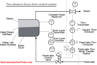
The Below Figure shows the control scheme for three-element drum level control. To the left of the dotted line, the instrumentation is the same as that for the two-element drum level control, with one exception: the output of the feedwater flow computer now becomes the set-point of the feedwater flow controller (FIC-2). Equipment required to complete our three-element drum level control scheme includes an additional flow device (FE-2) and differential pressure transmitter (FT-2).

Three Element Drum Level Control System
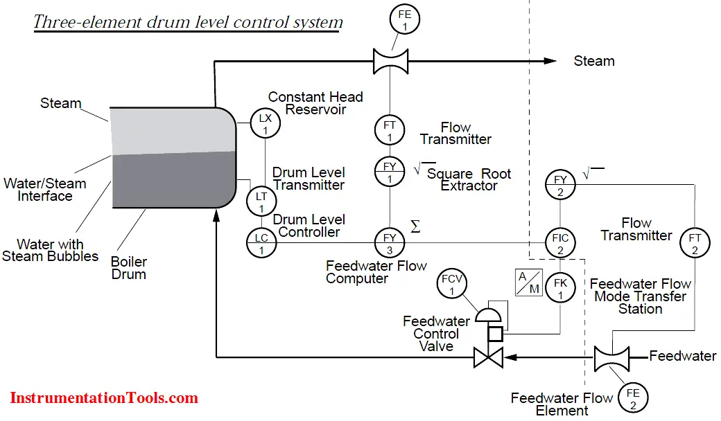
The area to the left of the dotted line in figure functions the same as that of a two-element drum level control. We can pick up the operation for this scheme where the output signal of the feedwater flow computer (the combination of steam flow and drum level) enters the feedwater controller (FIC-2).

This in effect becomes the set-point to this controller. Feedwater flow Is measured by the transmitter (FT-2). The output signal of the feedwater flow transmitter is linearized by the square root extractor, (FY-2) (Note: Now a days square root extractor function provided in either transmitter or controller as inbuilt option). This signal is the process variable to the feedwater controller and is compared to the output of the feedwater flow computer (set-point). The feedwater flow controller produces the necessary corrective signal to maintain feedwater flow at its set-point by the adjustment of the feedwater control valve (FCV-1).

As in the two-element drum level control scheme, nearly all of the work necessary to compensate for load change is done by the feed-forward system (i.e. a pound of feedwater change is made for every pound of steam flow change). The drum level portion of the control scheme is used only in a compensating role. Despite low-to-moderate volume/ throughput ratio and a wide operating range, it is expected the drum level will be maintained very close to set-point. Achieving this requires use of the integrating response and reset in both the drum level and feedwater controllers.

Source : ABB

Don't Miss Our Updates
Be the first to get exclusive content straight to your email.
We promise not to spam you. You can unsubscribe at any time.
Invalid email address
You've successfully subscribed !

Recommended Articles

VFD Simulator Download – Free Yaskawa V1000 Software
Automation System Process Functionalities
How to Do Logic Checks During Plant Pre-Commissioning
What is Maintenance Override Switch (MOS) ?
PID Controller Theory
Basics of Motion Controllers
Share This Article
Facebook Whatsapp Whatsapp LinkedIn Copy Link
Share
2 Comments
  • Rodolfo Redovan says:
    March 27, 2017 at 3:05 pm

    How to prevent carry over on the steam boiler main header?

    Reply
  • Qadir Mohtasham says:
    July 13, 2018 at 1:12 pm

    Good job

    Reply

Leave a Reply Cancel reply

Your email address will not be published. Required fields are marked *

Stay Connected

128.3kFollowersLike
69.1kFollowersFollow
208kSubscribersSubscribe
38kFollowersFollow

Categories

Recent Comments

  • William Snyder on Top Non-PLC Certification Courses for Automation Professionals
  • Kamli on Top Free PLC Software
  • Guifty Shimica on Top Non-PLC Certification Courses for Automation Professionals
  • Guifty Shimica on Top Non-PLC Certification Courses for Automation Professionals

Related Articles

Troubleshooting PLC Current Loops

Troubleshooting Current Loops with Voltage Measurement

Compare Serial and Parallel Communication

Difference Between Serial and Parallel Communication

Find the Fault in the Temperature Loop

Fault in the Temperature Loop

2 wire transmitter current loops

2-wire Transmitters Current Loops

What is Open Telemetry?

What is Open Telemetry? – Principles and Benefits

21 CFR in SCADA and HMI Systems

What is 21 CFR in SCADA and HMI Systems?

Industry 4.0 Explained

Industry 4.0 Explained – Industrial Internet of Things

DeltaV System Configuration Change and Download - 3

DeltaV System Configuration Changes and Download

More Articles

Questions and Answers on Valves

Valve Quiz

Economics of Power Generation Objective Questions

100+ Economics of Power Generation Objective Questions and Answers

Omron PLC Instructions - Move, Move Bit, Move Digit

Move, Move Bit, Move Digit – Examples of Omron PLC Programs

Ethernet Questions and Answers

Ethernet Communication Interview Questions & Answers

Bolted to Vessel Flange Displacer Level Transmitter

Seal Level Differential Pressure Transmitter Problems

SFC Language in PLC Programming

SFC Language in PLC Programming

Wedge Flow Meter

Wedge Flow Meter Principle

Midline output instruction

What is Midline Instruction in Siemens PLC?

Follow US
All rights reserved. Reproduction in whole or in part without written permission is prohibited.
Welcome Back!

Sign in to your account

Username or Email Address
Password

Lost your password?