The possibility of controlling the Induction motor’s speed exists only with the Variable frequency drives. Basically, there are three different modes through which we can control the speed of an induction motor.
- Using a digital signal
- Using an analog signal of 0 to 10V / 0 to 5 V/ 4 to 20mA / 0 to 20mA, etc.
- Using the Modbus communication whether on RTU mode or TCP/IP mode
Speed of Induction Motor
In this post, we will use an analog input signal with a range of 0 to 20 mA to control the motor’s speed. This article shows how to control the speed of the motor using PLC’s analog output. See the below schematic to get an overview.
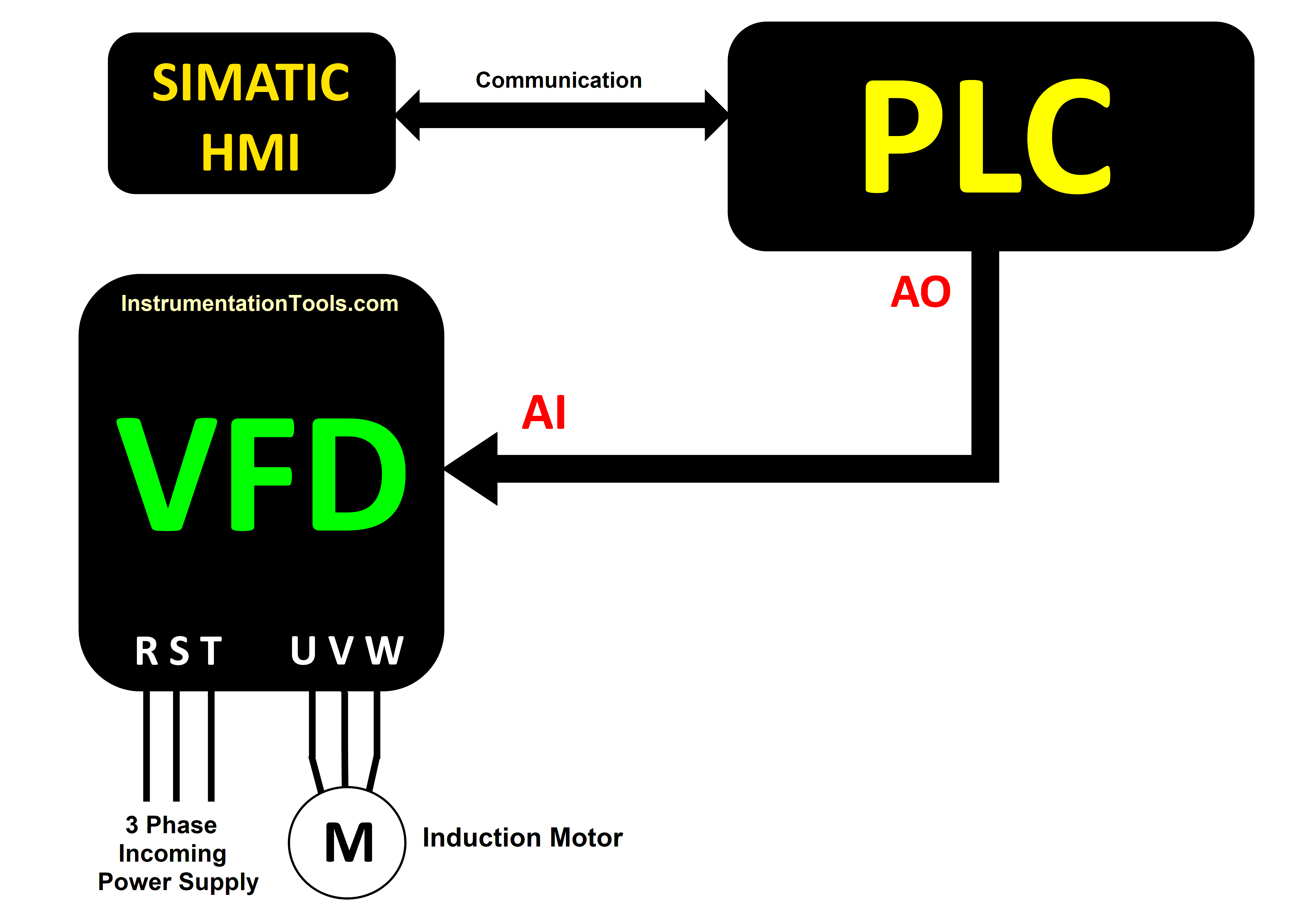
To change the motor’s speed, a 0 to 20 mA analog output signal from the PLC is sent into the analog input terminal of the VFD. The speed varies from 0 to 50 Hz as the milliamperes rise from 0 to 20. In this topic, we use six unique Analog Output points of the S7 200 smart PLC to control the speed of six motors. (each motor has individual VFD as per the motor rating).
The PLC used here is Siemens CPU ST60 of S7 200 Smart series having two analog output modules EM AQ04 coupled with it, while the VFD model is ATV310 series of Schneider Electric. Siemens HMI is communicated with CPU ST60 to vary the speed of the motors from its screen.
Prior to the PLC logic, see the hardware configuration and connection details below:
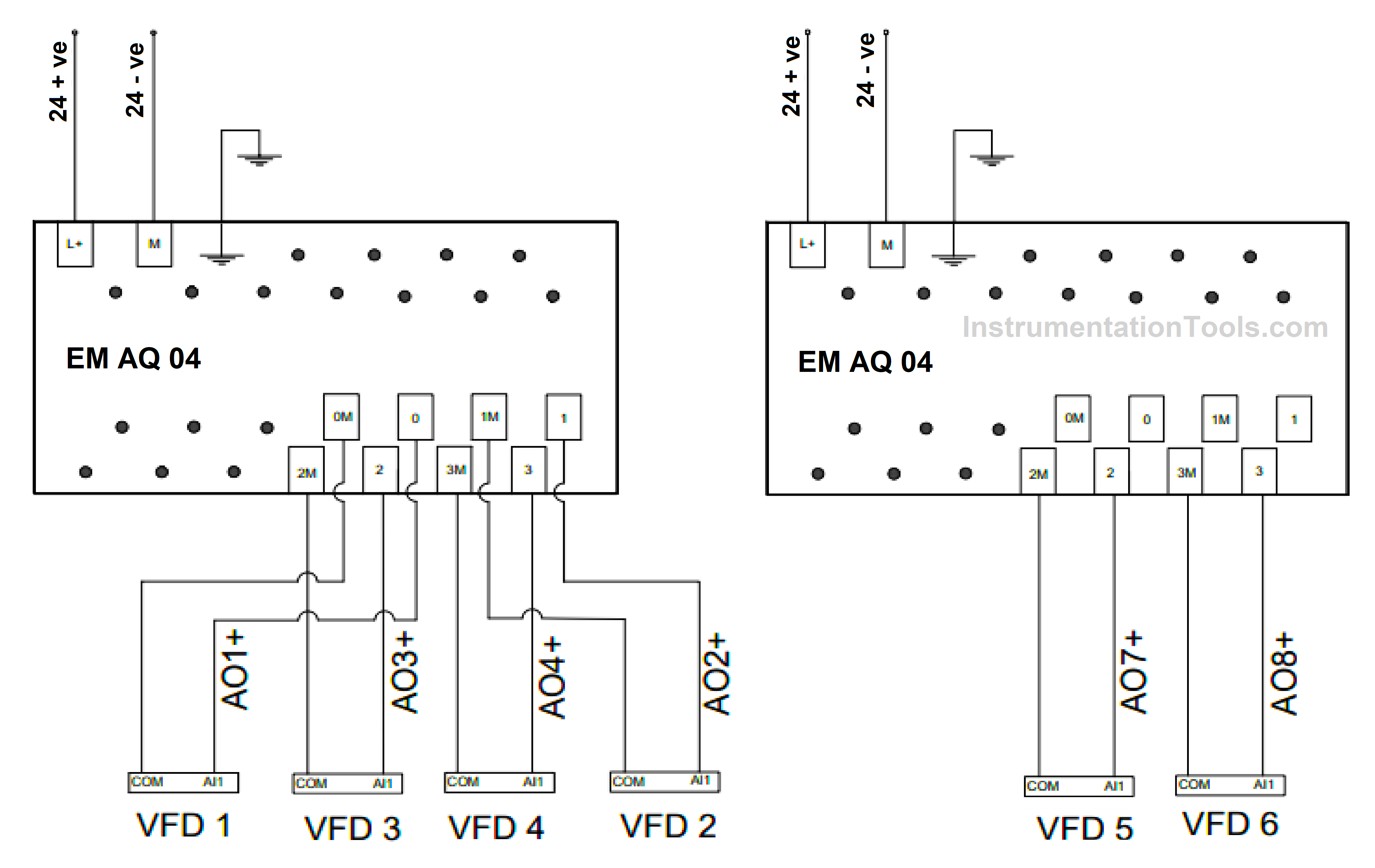
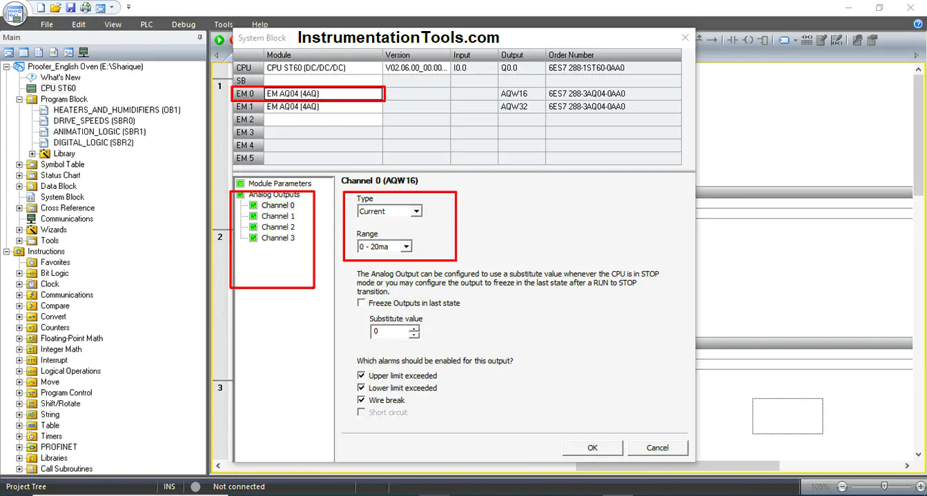
The above analog output modules are added to CPU ST60. Each analog input point of the VFDs will receive a 0 to 20 mA signal from various PLC analog output points.
Now, look at the parameter details of the ATV310 VFD drive.
- 401: 01 (Reference Channel 1)
- 204.0: 0A (AI1 type)
- 204.1: 4mA (AI1 current scaling parameter of 0%)
- 204.2: 20mA (AI1 current scaling parameter of 100%)
Apart from these, motor parameters need to be set in group no “300” according to the Motor rating.
The analog output module is also called the DA module or digital to analog module. According to this statement, a digital value is translated to milliamperes or voltage in accordance with the configuration setup.
Different PLCs have various digital values that can be converted into an analog voltage or milliampere signal. The Siemens S7 200 series uses 0 for 0 milliamps and 27648 for 20 milliamps.
In accordance with parameter number “204.1,” we must determine the digital value at which the output point emits around 4mA. By using the hit-and-miss method, we identified the value as “5559,” at which we received 4 milliamperes approximately.
According to the discussion above, the frequency would be anywhere between 0 and 50Hz, and the milliamperes in the PLC are represented as digital values. When a particular frequency is fed from HMI, some scaling is required to get the actual frequency.
So, we can call these digital values as “unscaled” values. Now to change these unscaled values to scaled ones, there is a formula below:
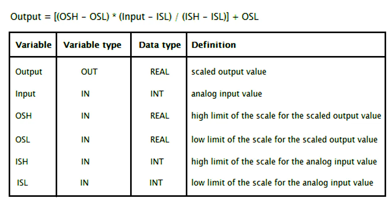
OSH = 27648.0 (Unscaled digital value to output 20 mA analog signal)
OSL = 5559.0 (Unscaled digital value to output 4 mA analog signal)
ISL = 0 (Lower limit of the frequency output in Hz)
ISH = 50 (Upper limit of the frequency output in Hz)
“Input” is the variable for setting the motor’s speed from HMI.
“Output” is the scaled digital value
Now, putting these values in the formula and evaluating further:
Output = [(27648.0 – 5559.0) *(Input – 0)/ (50 – 0)] + 5559.0
Output = [22089.0*Input /50] + 5559.0
Output = [441.78*Input] + 5559.0
Before evaluating the equation in the ladder logic, go through the Analog output configuration settings in the PLC software below:
In Step 7 MicroWin Smart software, Click on the highlighted System Block settings option available in the “project tree” bar.
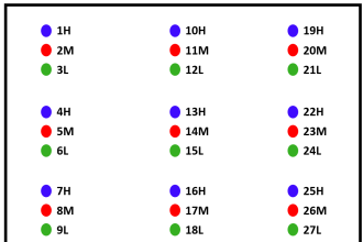
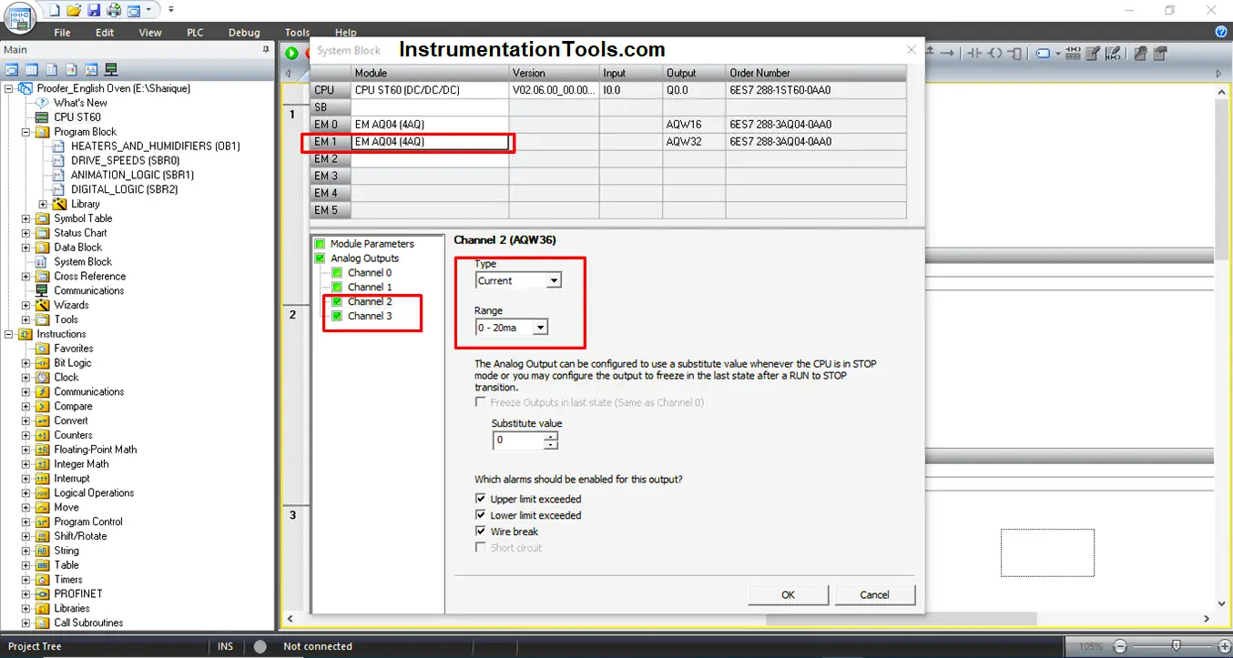
In the system block settings, configure all the channels of the first AQ04 card and the 3rd & 4th channels of the second AQ04 card with the current type as highlighted.
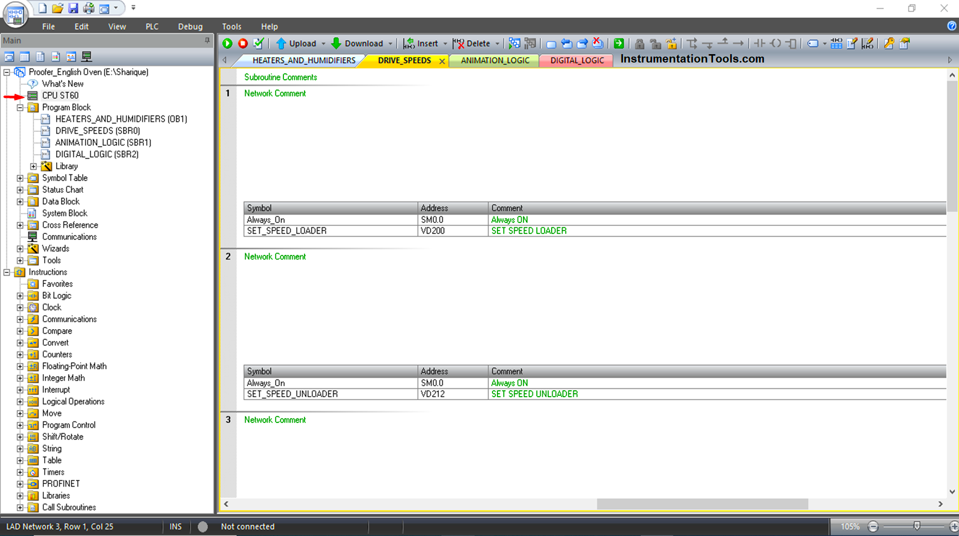
PLC Programming for Induction Motor Speed Control using Analog Output
Network 1:
VD200 stores the input value or variable value that is set from HMI in the form of frequency or Hz. It is then multiplied with 441.78 and stored in VD204.
The value in VD204 is then added with 5559 and stored in VD208.
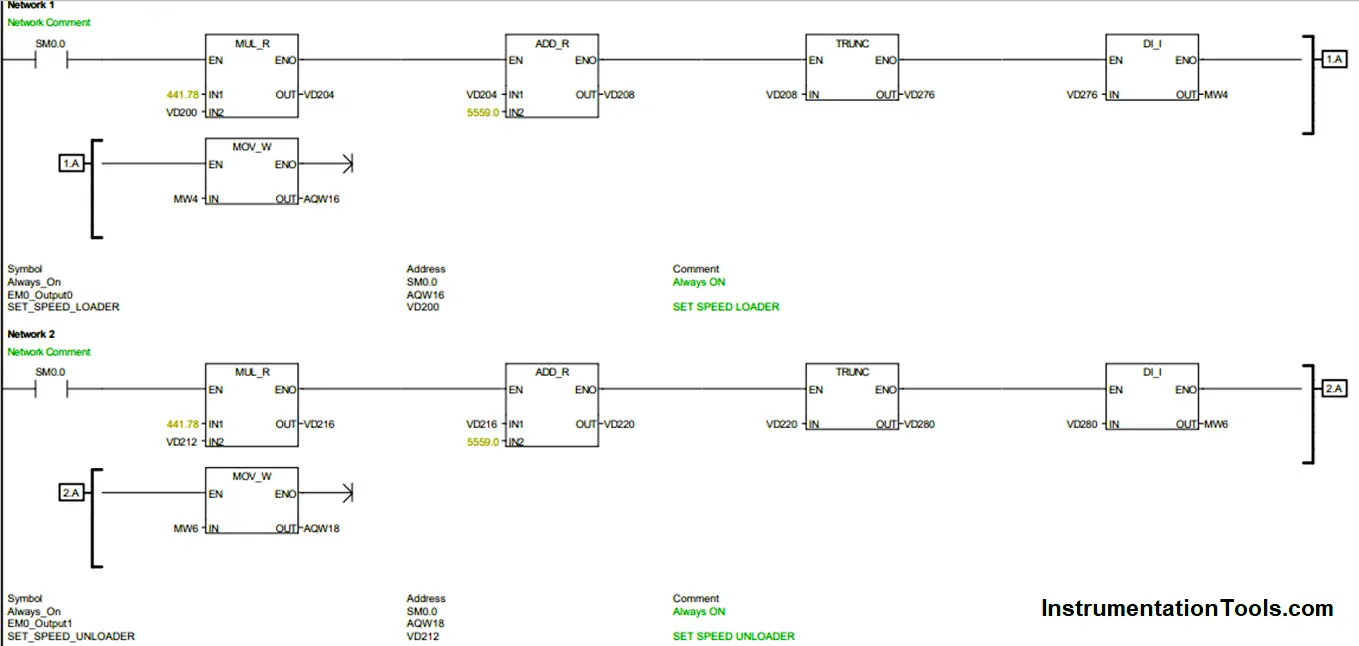
The value in VD208 is an evaluated scaled output value in real format. The fractional part of the value in VD208 is discarded and the whole number portion is stored in VD276 in the double integer format using the “TRUNC” instruction.
After that, MW4 stores this double integer value in integer format. The address for the first channel of the AQ04 module, AQW16, is where this value is now transferred.
Ex: If VD200 = 41.5 Hz fed from HMI then VD208 = [441.78*41.5] + 5559.0 = 23892.87.
Thus, to attain 41.5 Hz, 23892 is to be stored in MW4 in the form of integer.
As per the network comment, the first channel is used to vary the speed of the motor (Loader) in one of the applications.
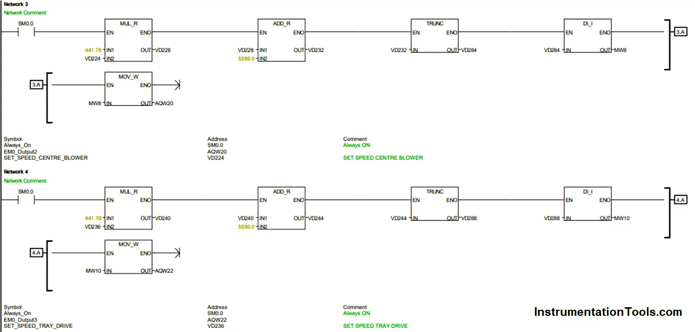
Similarly, networks 2 to 6 are build to vary the speed of other motors and fans from their respective channels of EQ04 modules using VD212, VD224, VD236, VD248, and VD260 as their variable speed set points.
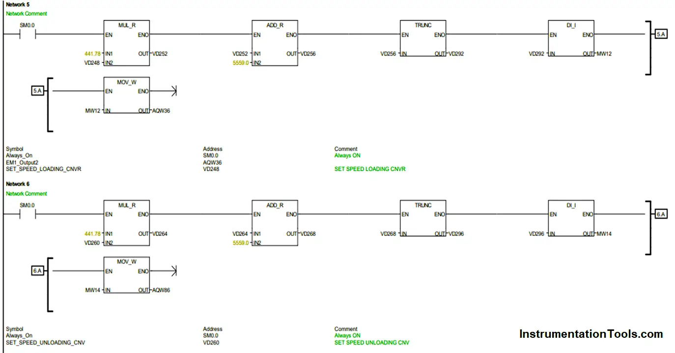
According to the wiring connections, the second EQ04 module uses the third and fourth channels; as a result, the addresses used are AQW36 and AQW38. To learn more, see System block configuration.
In the below video, you can see the VFDs and HMI. We can set the required motor speed through the HMI and then the VFDs will control the respective induction motor speed accordingly.
If you liked this article, then please subscribe to our YouTube Channel for Electrical, Electronics, Instrumentation, PLC, and SCADA video tutorials.
You can also follow us on Facebook and Twitter to receive daily updates.
Read Next:
- Comparison of Control Loops
- Top Best Practices of PLC Wiring
- Interposing Relay Panel Wiring
- Testing and Validation in PLC
- Site Commissioning Steps for PLC