Safety PLCs have great monitoring and diagnosis capabilities, which allow them to maintain the health of the safety function even if internal failures occurred. A safety PLC will detect the internal failure of any safety module connected to the safety control circuit.
One of the crucial aspects of any safety circuit is the acknowledgment step before allowing your process to run again. Safety standards dictate the need for acknowledging the safety condition before starting the process again.
This ensures that running the machine was enabled after an operator recognized the risk condition, cleared the risk, and acknowledged the safe operation once again.
In this article we will talk about one useful safety PLC instruction in TIA Portal; this is the ACK_GL or Global acknowledgment function.
Contents:
- What is Global Acknowledgement?
- What is passivation?
- When will a passivation occur?
- What is reintegration?
- What is F-I/O DB?
- Some of the important parameters of an F-I/O DB.
- Methods of reintegration.
- Important notes.
- Conclusion.
What is Global Acknowledgement?
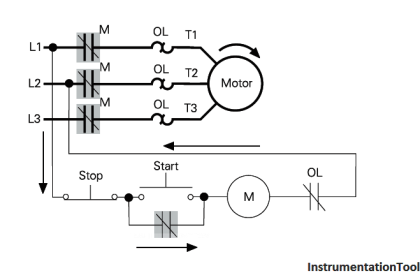
The acknowledgment step is one of the most important aspects of any safety control circuit, it simply means that if there is any risk condition that has occurred and stopped your machine, the machine can’t run again until an acknowledge signal is provided, even if the risk condition is cleared.
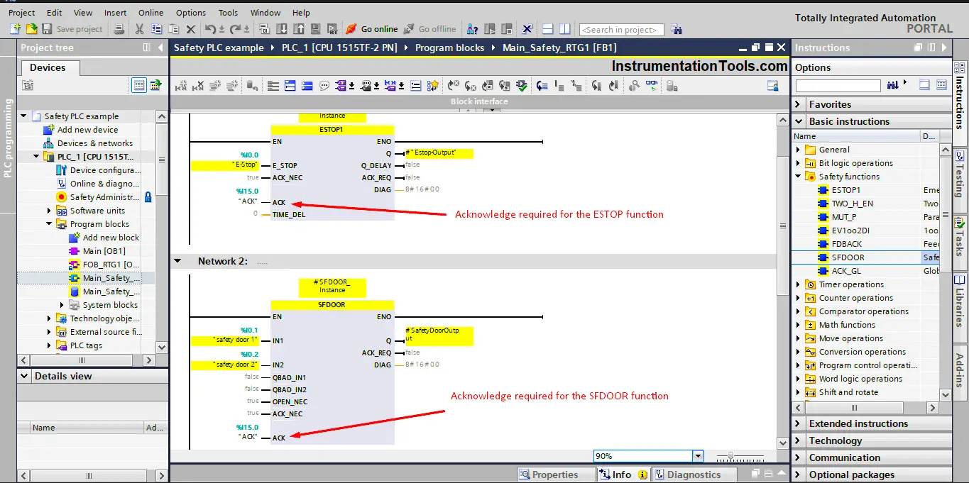
We saw in previous articles explaining different common safety functions like the ESTOP or the SFDOOR instructions, there was always an ACK signal that needs to be provided before the output can be ON again, even if the risk is cleared.
This is to ensure that whoever will acknowledge the safety condition will ensure that the machine can now safely start working again. See picture 1.
That was for the safety instructions, but what about the safety modules?
As you know, safety PLCs and their safety modules are designed, tested, and certified to comply with safety standards, which include diagnosis, monitoring, and redundancy of input and output signals and Self-diagnosis of internal software and hardware failures.
That means, when an internal failure in one of the safety modules occurs, the safety PLCs will detect that failure and the safety module will go into what is called passivation. Which means your process will probably stop.
And after you clear this fault, you will have to acknowledge the safety condition again before the system can run. The acknowledgment step of the safety input/output modules or F-I/O is known as reintegration.
What is Passivation?
When passivation occurs in an F-I/O with inputs, the safety PLC will provide the safety program with fail-safe values instead of the process data pending at the fail-safe inputs in the PII.
When passivation occurs in an F-I/O with outputs, the F-system transfers fail-safe values to the fail-safe outputs instead of the output values in the PIQ provided by the safety program.
After you clear this fault, you will have to perform acknowledgment or reintegration of the F-I/O again before the system can run.
When will a Passivation occur?
A passivation to an F-I/O will occur if any of the following cases are present:
- Start-up of the F-System.
- Communication fault between F-CPU and F-I/O.
- F-I/O channel fault (e.g. wire break, short circuit, discrepancy fault).
- Activating passivation of F-I/O in the F-I/O DB with PASS_ON = 1.
What is reintegration?
Reintegration for an F-I/O module with inputs, the process data pending at the inputs in the PII are provided again for the safety program.
For an F-I/O with outputs, the F-system again transfers the output values provided in the PIQ in the safety program to the fail‑safe outputs.
This can be done automatically or following user acknowledgment in the F-I/O DB depending on the hardware configuration of the module, but the safety standards insist on making it with an acknowledgment.
What is F-I/O DB?
as we mentioned before, any safety module whether it is a safety input module or a safety output module will have built-in self-monitoring and diagnoses functions, these functions run in the background, to ensure the safe operation of your module.
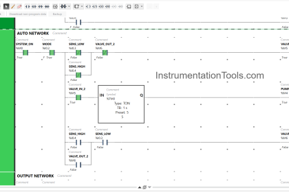
An F-I/O DB is the built-in dedicated data block that is used by the safety PLC to store related data of the safety module. See picture 2.
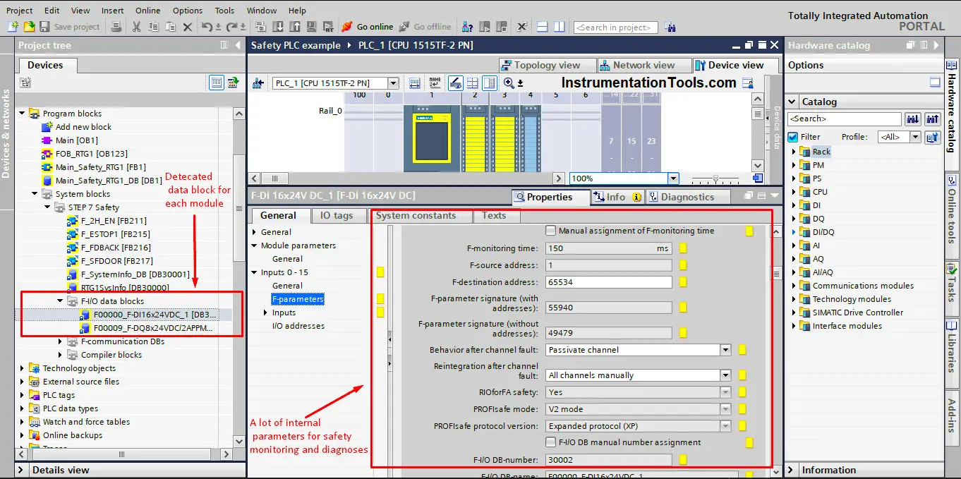
As you can see from picture 2, each safety module has a lot of internal parameters and configurations related to the monitoring and redundancy of the module, and each safety module will have a data block or a DB. To store these data inside. See picture 3.
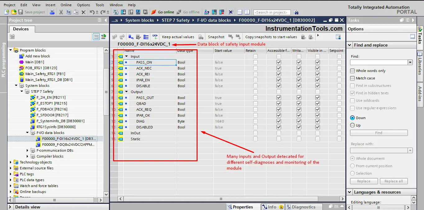
As you can see from picture 3, the DB of the safety input module, has a lot of parameters inside, these parameters provide all data related to the safety module.
Some of the important parameters of an F-I/O DB:
- PASS_ON: this input bit will activate a passivation of the related module if it was set to 1.
- ACK_REI: you can use this input bit to manually acknowledge the passivation of the related module, meaning if you set this bit to 1, the passivated module will be acknowledged for reintegration.
- PASS_OUT: this output bit will be TRUE if the related module is passivated.
- DIAG: This is an output WORD that is used to store diagnostics data, if there is a fault in the module, this will take a value related to this fault, then you can refer to the help tables to find out what this fault means.
Methods of Reintegration
For example, if one of the safety input modules F-DI was taken out of the power rail, the safety PLC will pick up this fault and stop the process until the safety input module is put back into its place, but even then the process will not start until you acknowledge the F-DI for reintegration as we mentioned before.
If an F-I/O fault is detected by the F-I/O, the passivation of the relevant F-I/O will occur. Once the F-I/O fault or channel fault has been eliminated, reintegration of the relevant F-I/O should be done. You can assign a reintegration by user acknowledgment either two way.
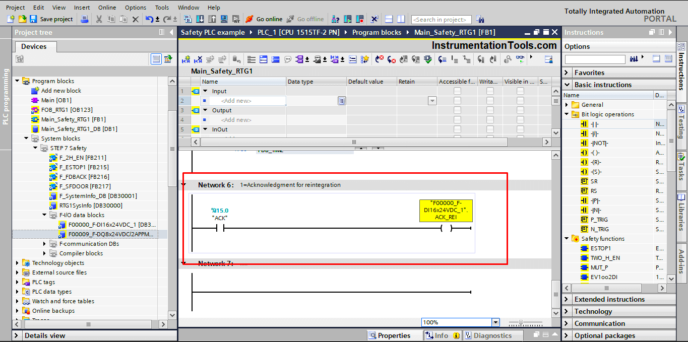
- Reintegrate each F-I/O separately:
As we said before, we can use the ACK_REI bit of the related safety module to separately reintegrate this module when it is passivated.
If passivation has occurred, you will need to a rising edge trigger with the ACK_REI bit after you clear the module fault. See picture 4.
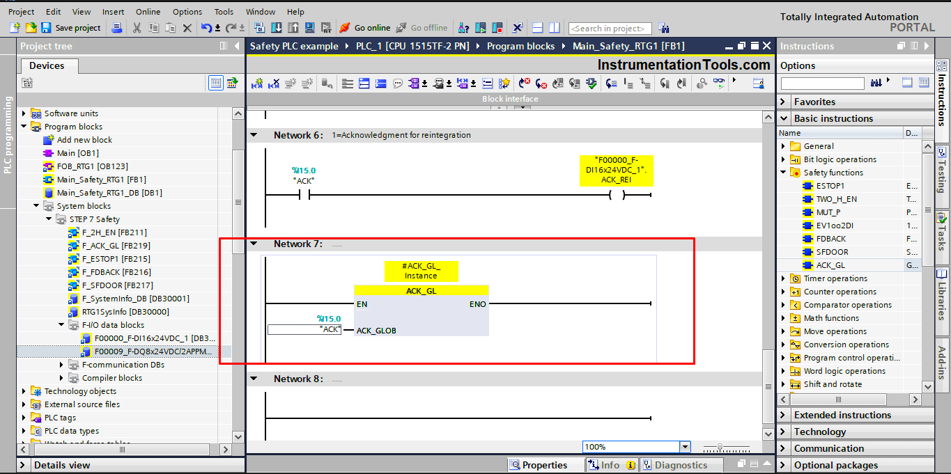
- Globally reintegrate all safety modules F-I/O at the same time:
The ACK_GL or Global acknowledgment instruction creates an acknowledgment for the simultaneous reintegration of all F-I/O or channels of the F-I/O of an F-runtime group after communication errors, F-I/O errors, or channel faults. So you wouldn’t have to separately reintegrate each module. See picture 5.
Important Notes
- An acknowledgment via the ACK_GL instruction is only possible if the tag ACK_REI of the F-I/O DB = 0. Accordingly, an acknowledgment via the tag ACK_REI of the F-I/O DB is only possible if the input ACK_GLOB of the instruction = 0.
- ACK_GL cannot be used to acknowledge other common safety functions like ESTOP or SFDOOR, for these instructions the ACK_GL will not be useful. You will have to acknowledge these instructions by giving a rising edge at the ACK bit as shown in picture 1.
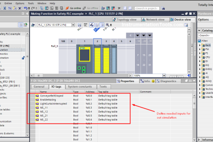
- You can use the same bit to acknowledge safety modules separately, to set the ACK_GL, or to acknowledge other safety functions like ESTOP or SFDOOR, check the previous picture, you will see that we used %I15.0 for all acknowledgments.
Download the Safety PLC logic in PDF and the source code in the TIA portal.
P.S. password for the safety PLC code is 123
Conclusion
Safety PLCs provide many safety functions that are built in to ensure the safe operation of your process while considering all safety issues employed by the standards.
You can program all these safety functions using a normal PLC, but your code will be so large that you might miss some details, also, a normal PLC will not provide the internal monitoring and diagnoses that the Safety PLC provides.
Of these safety functions, there is global acknowledgment. It is very simple to use, but very important and critical for the safety of your process. And it mainly depends on the great monitoring and diagnosis capabilities of the safety PLCs.
If you liked this article, then please subscribe to our YouTube Channel for Instrumentation, Electrical, PLC, and SCADA video tutorials.
You can also follow us on Facebook and Twitter to receive daily updates.
Read Next:
- Delta PLC & VFD Modbus
- HMI for Your Application
- SCADA System Vulnerabilities
- Difference between PLC and HMI
- Controlled Development System