In a previous article, we talked about safety control circuits and how important are they for ensuring a safe environment for workers in industrial processes. And we also give a simple example for coding an emergency push button using a safety PLC with the TIA Portal platform.
In this article, we will show how to code another very common and important safety function, which is the safety door interlock switch, and how to integrate it into your normal process coding.
Contents:
- Problem description.
- Hardware configurations
- Programming steps.
- Code simulation.
- Conclusion.
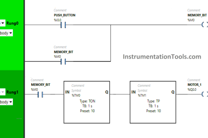
Safety Door Interlock PLC Program
You have a process or a part of a machine that is set up inside a closed section to prevent workers from going inside while the machine is running for their safety.
There is, of course, a door installed for this closed section and on that door, we have a safety interlock switch to indicate if the door is opened or closed so that the safety control circuit would take appropriate action to ensure the safety of the process.
The most common setup of a safety door interlock is the two opposite limit switches installed on the door in such a way that only one of them will be closed when either the door is opened or closed, as shown in the following picture.
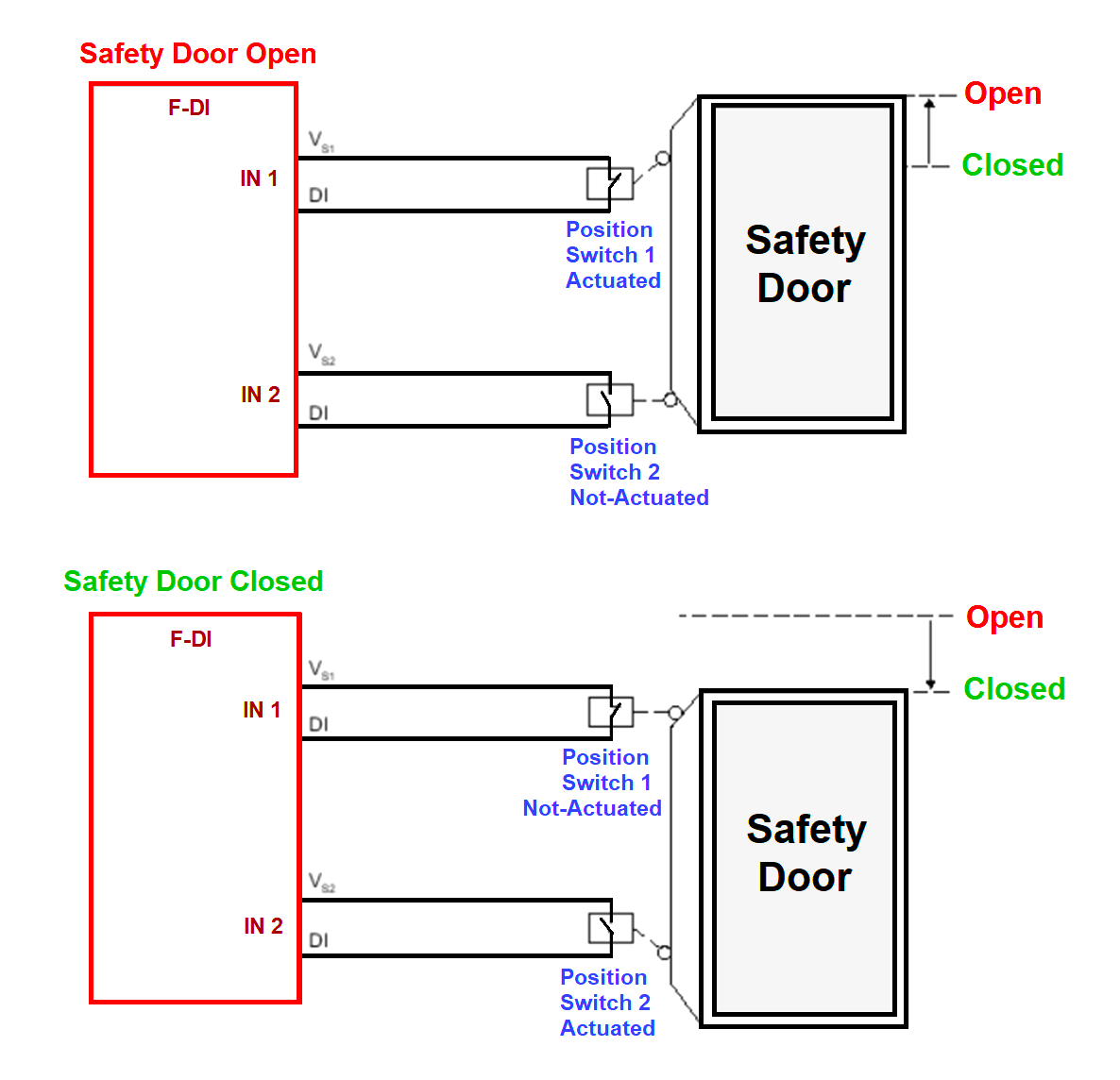
As you can see from picture 1 when the door is open switch 1 will be activated and switch 2 will be open. And when the door is closed it will be the opposite, switch 1 is open and switch 2 is closed.
This setup is used to provide an extra level of safety and monitoring as both switches can’t be closed or opened at the same time, and if that happened then it would mean a failure in one of the switches which will trigger the safety function.
Another thing you should know is that for redundancy reasons switch 1 and 2 might be the dual-channel switch, meaning each switch will have two identical and separate channels.
In this example we will assume that each switch has dual channels, so now the safety PLC will monitor the system as follows:
- Safety PLC will monitor the dual channels of each switch against each other, they have to be in the same position all the time, and if not then there might be a failure inside this switch.
- Safety PLC will monitor the two switches 1 and 2 against each other; they have to be opposite to each other all the time, if not, then there might be a failure inside one of them.
In either case, the safety PLC will trigger the safety function until all safety conditions are restored and acknowledged.
Safety PLC Hardware Configuration
As we did in the previous article, we will add a safety input module, and safety output module, and a standard input module for the ACK button.
We have two switches with each having dual channel contact, we will connect switch 1 to channels 1, and 9 and switch 2 to channels 2, and 10 in the safety input module. See picture 2.
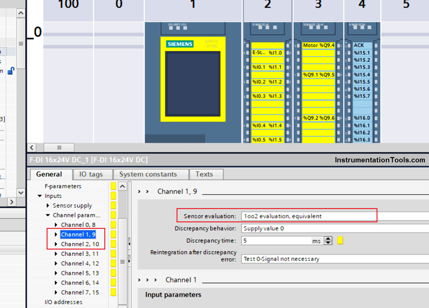
Remember that, we have a dual-channel switch, which is why each switch is occupying two channels in the safety module.
The 1oo2 evaluation, equivalent highlighted in the picture, is set like that so the safety PLC will monitor the two channels against each other as we mentioned before, to detect any internal failure in the switch.
Safety PLC Programming Steps
Define your input tags. See picture 3.

We will define switch 1 as safety door 1 in %I0.1 and switch 2 as safety door 2 in %I0.2
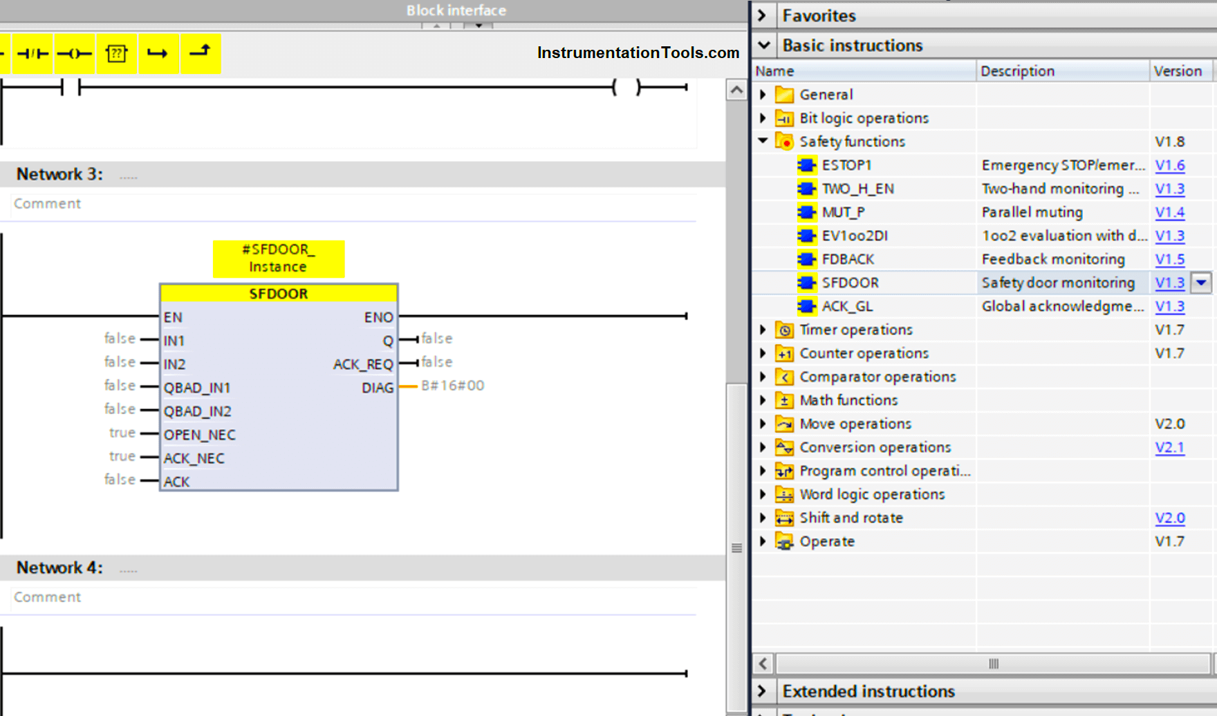
Next to the programming part, open your safety function block Main_Safety_RTG1 FB and inside the function block add SFDOOR safety door instruction block, see picture 4.
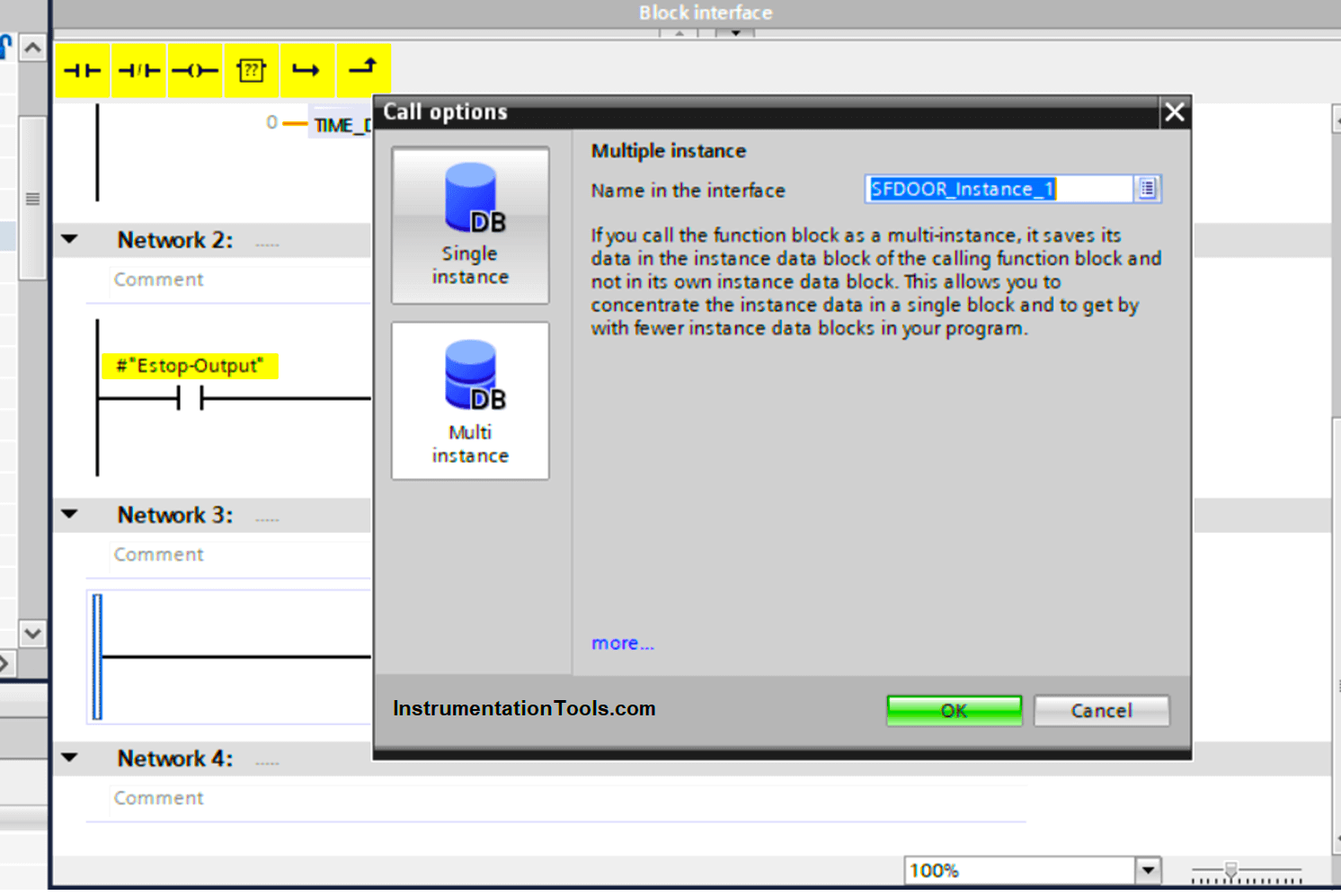
Note that, when adding an SFDOOR block you will be asked about the type of instance calling option, what you choose doesn’t affect the program coding, but choosing a multi-instance data block will ensure all data related to the SFDOOR block will be stored inside the main calling function, it is better for more organized and easy to read program, see picture 5.
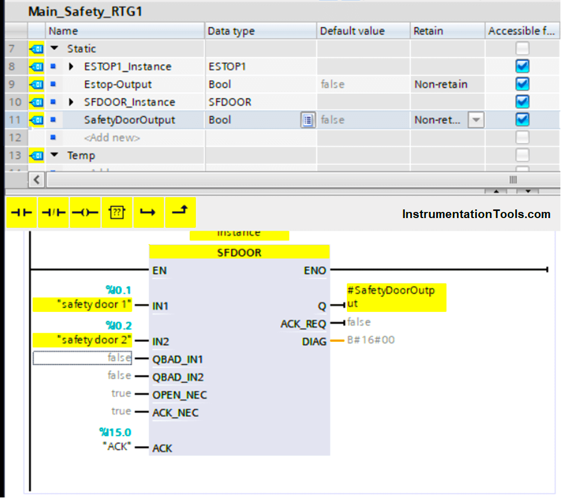
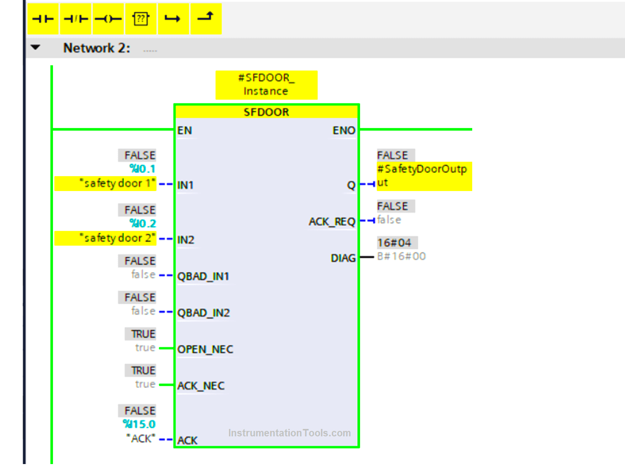
Now add your inputs to the instruction block, and also create a static output named SafetyDoorOutput and connect it to the instruction output, see picture 6.
Important Notes on the SFDOOR block
- QBAD_IN1 and QBAD_IN2
QBAD_IN1 and QBAD_IN2 are internally built functions inside the SFDOOR block to monitor if IN1 and IN2 are 0 merely due to the passivation of the associated F-I/O.
You can refer to the TIA Portal for help with more information on QBAD_IN1 and QBAD_IN2 and how to use them.
- OPEN_NEC
It means open necessary at startup, if set to true, then the door must be open and closed at start-up before you can start your process.
OPEN_NEC must not be set to false unless you have another enabling signal to prevent the process from automatically restarting after closing the door.
- ACK_NEC:
it defines whether your block will need an ACK signal before setting the output to ON or not. If it is set to false, then the block will automatically be acknowledged after the IN1 and IN2 are set to normal operating conditions, meaning the door is closed.
If you still don’t get this point: it simply means, the process can’t start again even after the door is closed until a start signal arrives once again.
Add safety door output with the emergency condition to the motor output. See picture 7.
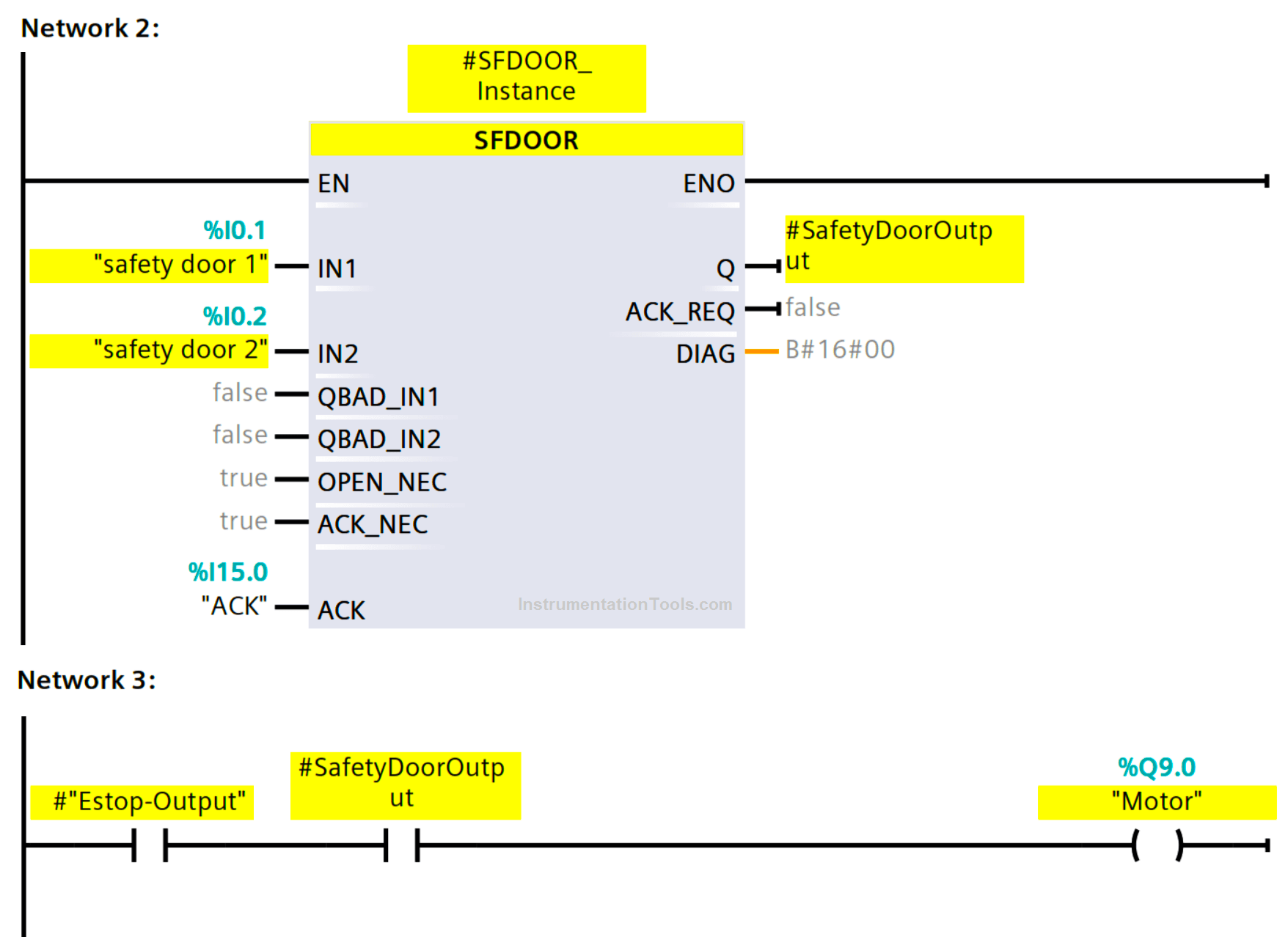
The safety control circuit is now complete, and the motor will not work if there is an emergency or if the door is open.
The motor also will not work if the safety PLC detects an internal failure in one of the safety door switches or the emergency push button.
Safety Door PLC Logic Simulation
Now, start a new simulation and experiment with your code. See picture 8.
Note that, at first power on, OPEN_NEC is required, because it was set to true, so the door must be opened and closed again.
It is worth mentioning that the internal functionality of the SFDOOR block expects that the change in the states of switch 1 and switch 2 will happen at the same time or very close to each other.
So if there was a time lag between the changing of the state of switch 1 and switch 2 the safety function will be triggered and the output will not be ON. So when you run the simulation make sure you activate both switches together at the same time.
As you can see, there is still no output, because we need to open and close the door first, let’s do that. See picture 9.
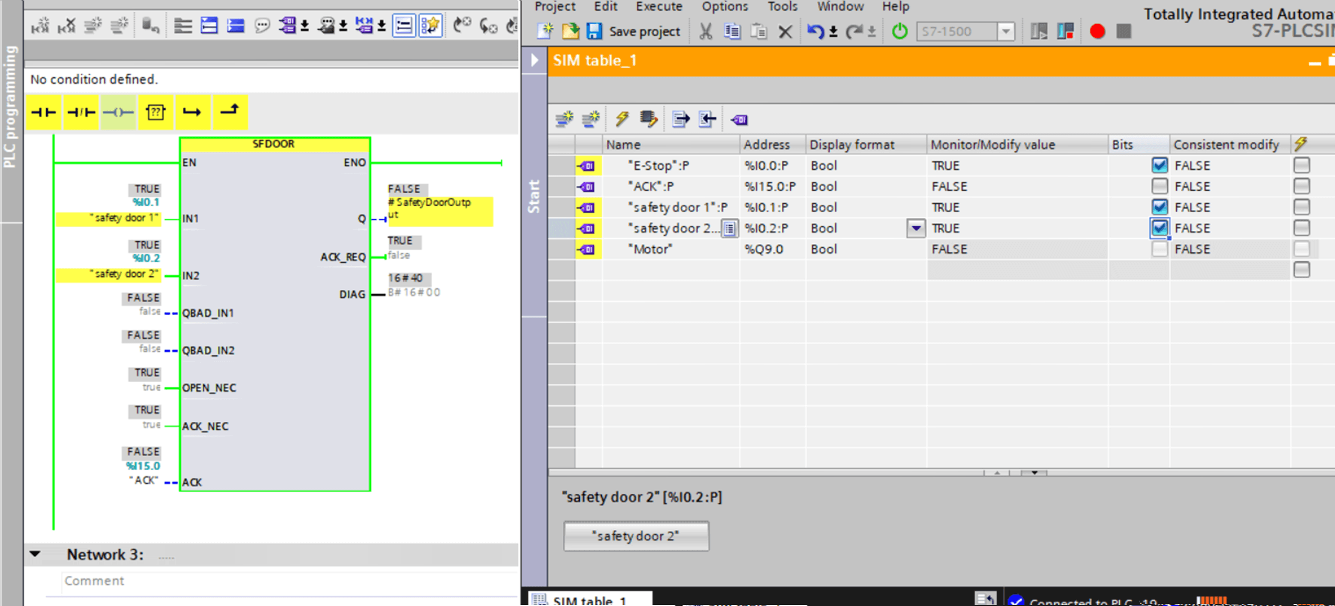
After opening and closing the safety door, we see that there is still no output because as we mentioned before, we have to acknowledge the closing of the safety door through the ACK input.
You can even see the ACK_REQ is set to true, meaning you need to acknowledge the safety function. See picture 10.
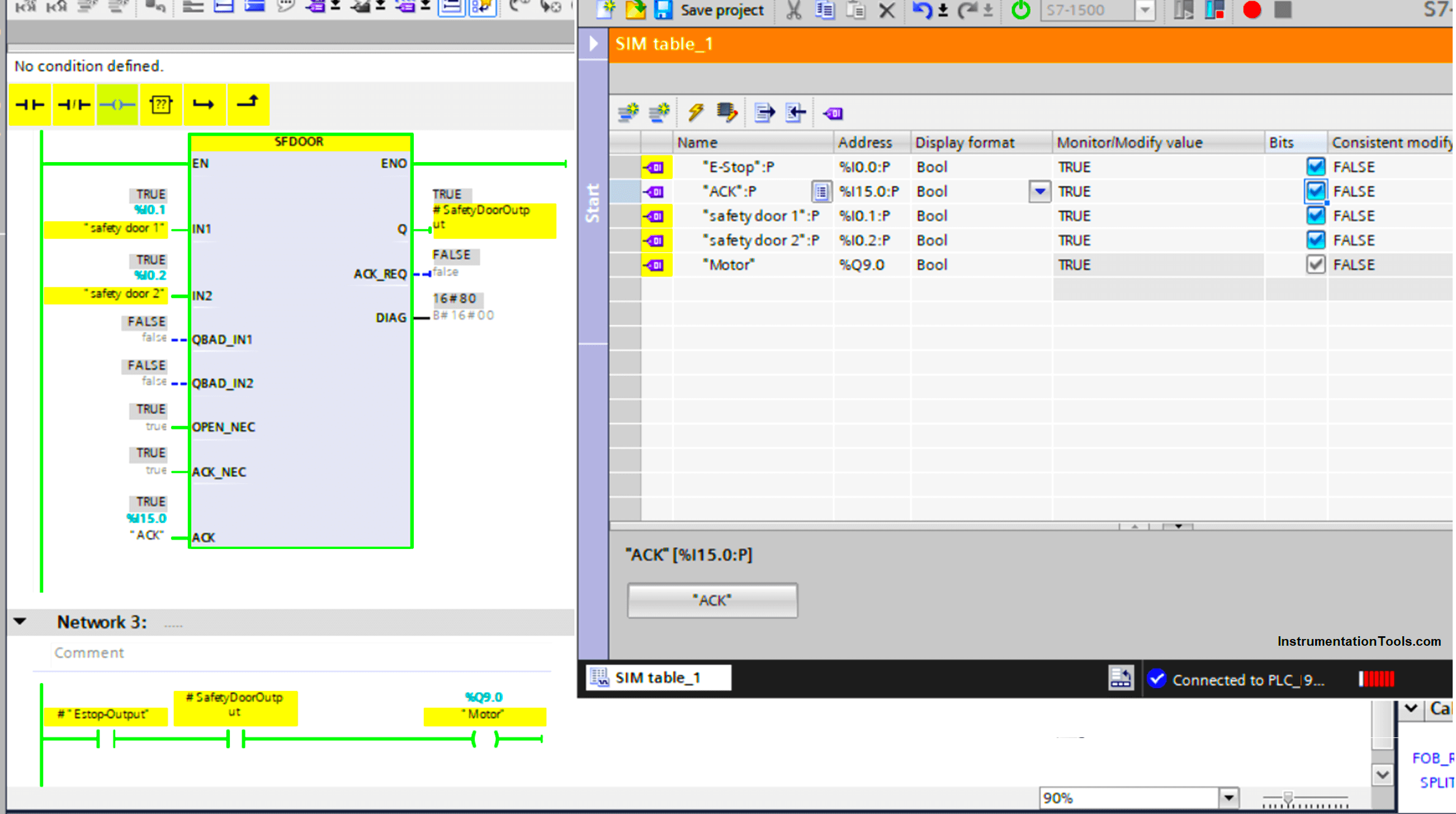
From picture 10 you can see that now the output is ON after the ACK button was pressed.
Free to download the safety door PLC code in PDF format and the original program in the Siemens Tia portal.
Conclusion
As you can see, programming a safety function using a safety PLC doesn’t really include a lot of programming, because as we said before, safety PLCs are designed and standardized to ensure safety.
So a lot of the safety functions that you would need to program from scratch when using a standard PLC are already standardized internally when using a safety PLC.
If you liked this article, then please subscribe to our YouTube Channel for Instrumentation, Electrical, PLC, and SCADA video tutorials.
You can also follow us on Facebook and Twitter to receive daily updates.
Read Next:
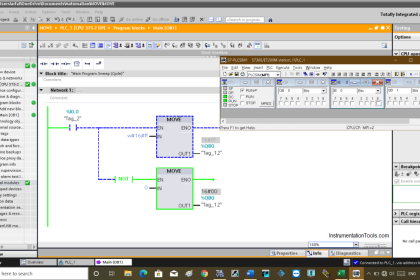
- MOVE Instruction in PLC
- PLC Best Practices & Tips
- How to Choose an HMI?
- Comparison of PLC & HMI
- Automation Engineering