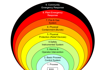
Safety Instrumented System (SIS) – Inline testing is quite useful for SIS instruments, and valves. Online testing enables the safe Operation & functioning of SIS.
In this article, testing refers to Proof testing of the SIS instruments/valves.
SIS Inline Testing
Inline testing implies that testing can be accomplished without a process shutdown. There are several requirements to be considered for accomplishing this.
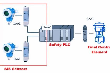
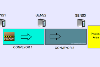
- Redundancy is mostly used for SIS components (especially sensors) wherever possible based on configuration. A test of one SIS sensor can be done, while the other sensor(s) continue to function.
- Bypasses could be installed around SIS final elements (valves) so that testing and maintenance can occur while the process is in operation.
- In batch plants, Inline testing might be accomplished by shutting down one train of equipment while keeping the rest of the plant running to eliminate (or reduce) any potential production loss,
- Documenting occurrences where the required automatic action has occurred during the operation of the plant (such as a pump trip, based on the same process condition that is required by the LOPA function).
- Automated testing and recordkeeping may be an option in some plants for a subset of the testing requirements, but all aspects of testing requirements (including visual field inspection of the installation, leak testing, etc.) must be met according to the required/calculated proof test interval.
Benefits of Inline Testing
The benefits common to all of the options above are to minimize downtime and reduce maintenance costs for SIS proof testing.
Automated inline testing (Like triggering the small movement of the valve say 2-3% using Smart Digital positioners) may bring value by extending or eliminating off-line proof testing, but may require additional instruments for comparison like Secondary flow/pressure transmitter or Master flow meters, etc.
Flowmeters Inline Testing
For simple DP cell and orifice plate types, the most common approach is to inject a differential pressure signal, simulating the flow, into the cell, however, this does not test the impulse lines and isolation or equalization valves for possible blockage.
Regular maintenance, impulse lies flushing & draining on a redundant sensor, and calibration of the sensor instrumentation enhance the inline testing and the reading from the instrument.
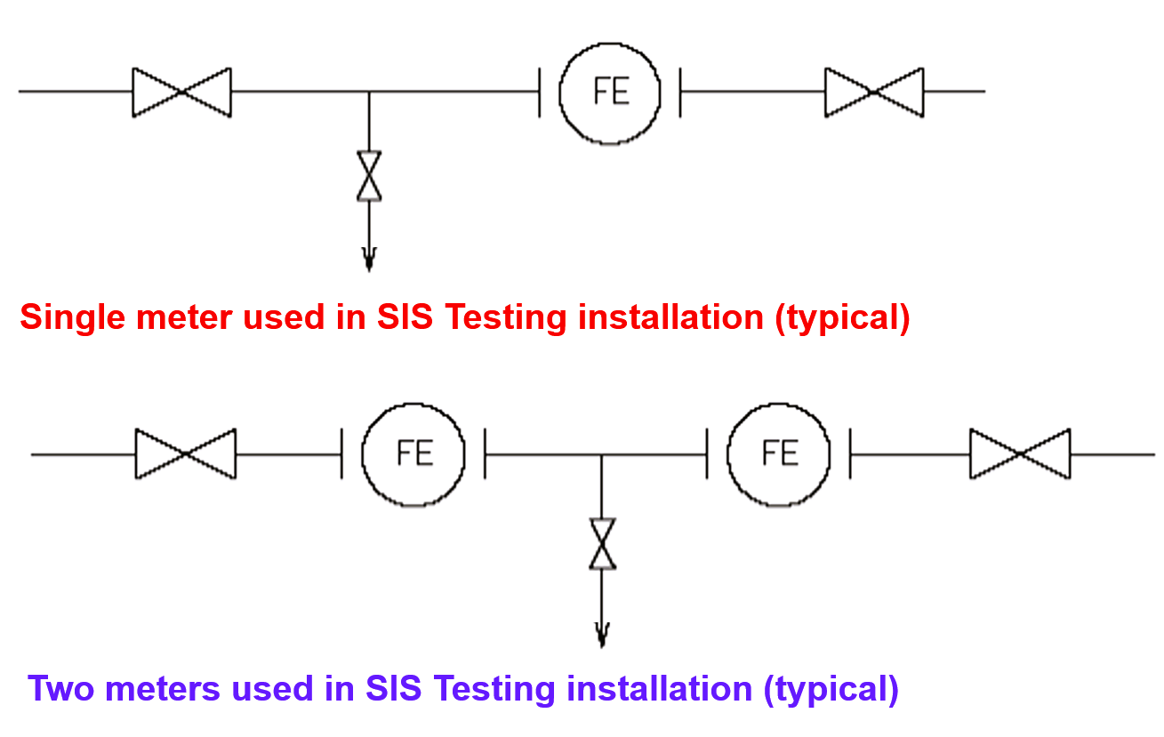
Flowmeter installations must include the necessary configuration to allow the proof testing of the instrument at the required testing interval.
The type of installation required will depend on the required test interval and the desired shutdown interval for the plant.
The following 1 line drawings are examples of installations that allow testing to be accomplished for single and two flow meters installations.
Temperature Elements Inline Testing
Temperature Elements installed in pockets of a process gas heater/furnace are tested online, as most of these installations form part of triple redundant systems with 2 out of 3 votings.
They use a thermocouple / PT100 simulator from the connection at the head and check for ingress, integrity, and connection security.
When inline, the technician check for differences in readings between the three instruments to detect drift.
To improve confidence and reliability, the maintenance team shall plan to change the thermocouples regularly in addition to simulation and check contact with the end of the pocket.
Another method of inline test is to inject a current, voltage, or resistance signal to simulate temperature and so test the operation of the safety system.
The signal can be injected into some types of probes together with the electronics and so only the sensing element is not tested.
On some other probes, the signal is injected after the electronics, particularly where the installations are on higher elevations & unreachable locations.
SIS Inline Testing of Valves
There is always a challenge to test the SIS Valves inline, as they form the critical isolation point of an equipment/process / interplant.
Why is it important?
With periods between plant shutdowns being extended, emergency shutdown valves (ESDV) may remain in the open position, without movement, for lengthy periods.
Experience has shown that after extended periods without movement, there is a tendency for the valve to stick.
This would result in the shutdown system failing to operate in the event of a genuine demand on the shutdown system, despite all other tests on the system being completed satisfactorily.
How to Overcome this?
An inline testing application such as Smart Valve Monitoring (SVM) can monitor the Emergency Shutdown Valve (ESDV) for faults based on comparing an original full closure fingerprint of the ESDV assembly and components, such as solenoid valves, against a partial stroke test.
Their system can perform all tests at the ESDV-designed closure speed without shutting the plant down.
Procedures to Test
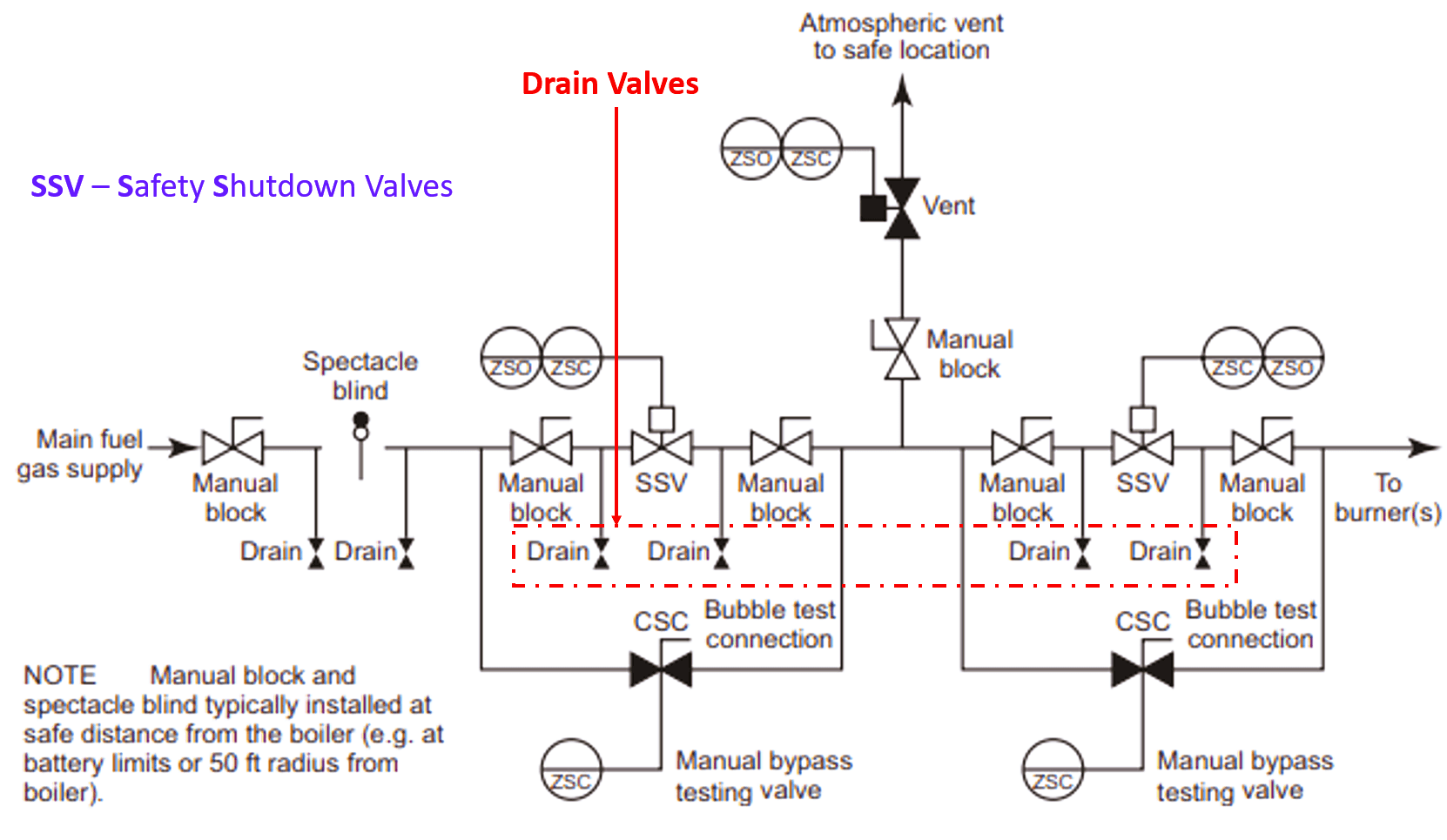
Adding drain valves where SIS Final control elements are in place. Below typical drawing depicts the installation/requirement.
This helps to inject instrument air at the upstream and ensure no leak in the ESD valve downstream,
An alternate method is to test ESD valves in-line by blocking the solenoid vent with a pressure gauge and operating the valve.
This caused the valve to move slightly and also gave an indication of the pressure gauge of solenoid operation.
This is not a standard practice. This system may work well though the installation and subsequent removal of the gauge would need to be very carefully controlled.
Another method is that valves can often only be tested when the plant is being shut down or actually shut down.
Tests are generally limited to tripping the valve and observing that it moves to the open or closed position. This test realizes that they can only carry out limited checks on the effect on flows through the valve if there is no bypass.
Digital Valve Controllers
The most efficient way to perform SIS Valves inline testing is to install Digital Valve Controllers (DVC).
DVC enables the user to define a suitable online valve stroke value from 1% up to a maximum of 30% from its standby position to minimize the effect on the process.
The test parameters are saved in the microprocessor’s non-volatile memory, minimizing mistakes and enabling consistent test results.
Digital Valve Controllers not only provide intelligence benefits in terms of performance and safety by allowing partial stroke test online but also provides additional benefits in terms of ease, simplicity, flexibility in diagnostics, improved reliability of SIF, etc.
By eliminating expensive conventional local test mechanism, which was laborious, time-consuming, and require specific talent.
Digital Valve Controller reduces complexity and simplifies the test process. Digital Valve Controller predictive maintenance capability provides complete Final Element health analysis and reduces the amount of scheduled regular maintenance by extending the turnaround period.
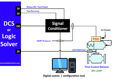
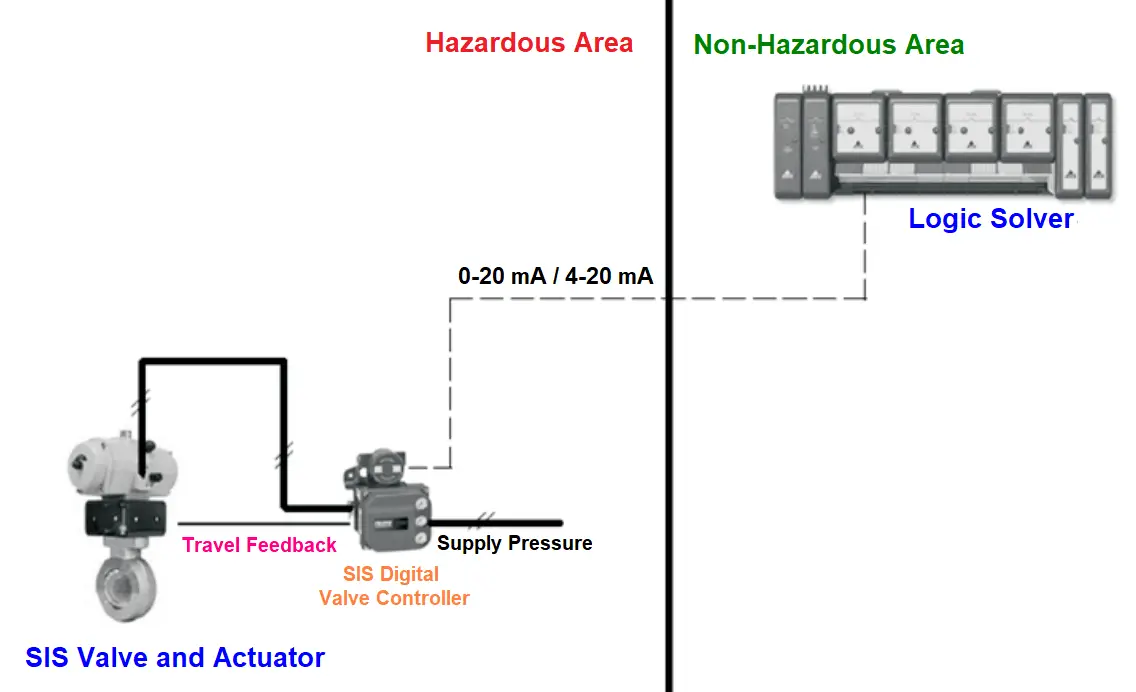
The below figure depicts a digital valve controller installed in a SIF loop, where Logic Solver provides an AO (Analogue Output) 0-20mA or 4 to 20 milliamp DC current signal to DVC. The signal is generated based on sensors and logic internal by the logic solver to DVC. Digital Valve Controller is used as a safety and Diagnostics device.
The below figure shows the SIS valve test schematic with a Digital valve controller using AO (4-20mA) signal.
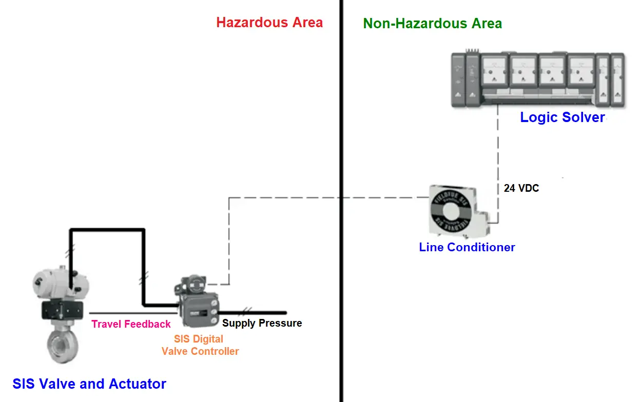
The below figure shows the SIS valve test schematic with a Digital valve controller using DO (24 VDC) signal.
Images Courtesy: Emerson
If you liked this article, then please subscribe to our YouTube Channel for Electrical, Electronics, Instrumentation, PLC, and SCADA video tutorials.
You can also follow us on Facebook and Twitter to receive daily updates.
Read Next:
- SIS Application Program
- How to do a Proof Test?
- Common Cause Failures
- SIS Verification & Validation
- Probability of Failure on Demand