Inst ToolsInst ToolsInst Tools
  • Courses
  • Videos
  • Q & A
    • Interview
      • Instrumentation
      • Electronics
      • Electrical
      • Practical Questions
    • MCQ
      • Instrumentation MCQ
      • Electrical MCQ
      • Electronics MCQ
      • Control Systems MCQ
      • Analog Electronics MCQ
      • Digital Electronics MCQ
      • Power Electronics MCQ
      • Microprocessor MCQ
      • Multiple Choice Questions
  • EE
    • Electronics
      • Electronics Q & A
      • Electronic Basics
      • Electronic Devices & Circuits
      • Electronics Animation
      • Digital Electronics
    • Electrical
      • Electrical Basics
      • Electrical Q & A
      • Power Electronics
      • Electrical Machines
      • Electrical Animation
      • Power Systems
      • Switchgear & Protection
      • Transmission & Distribution
  • Measure
    • Control Valves
    • Calibration
    • Temperature
    • Pressure
    • Flow
    • Level
    • Analyzers
    • Switches
    • Vibration
    • Solenoid Valve
  • Control
    • PLC Tutorials
    • Control Systems
    • Safety Instrumented System (SIS)
    • Communication
    • Fire & Gas System
  • More
    • Design
    • Tools
    • Animation
    • Basics
    • Formulas
    • Standards
    • TextBooks
    • Common
    • Software
    • Excel Tools
    • Erection & Commissioning
    • Process Fundamentals
    • Videos
    • Books
Search
All rights reserved. Reproduction in whole or in part without written permission is prohibited.
Reading: Ammonia Flash Vessel All Level Instruments Stopped Working
Share
Notification Show More
Font ResizerAa
Inst ToolsInst Tools
Font ResizerAa
  • Courses
  • PLC Tutorials
  • Control Systems
Search
  • Courses
  • Videos
  • Q & A
    • Interview
    • MCQ
  • EE
    • Electronics
    • Electrical
  • Measure
    • Control Valves
    • Calibration
    • Temperature
    • Pressure
    • Flow
    • Level
    • Analyzers
    • Switches
    • Vibration
    • Solenoid Valve
  • Control
    • PLC Tutorials
    • Control Systems
    • Safety Instrumented System (SIS)
    • Communication
    • Fire & Gas System
  • More
    • Design
    • Tools
    • Animation
    • Basics
    • Formulas
    • Standards
    • TextBooks
    • Common
    • Software
    • Excel Tools
    • Erection & Commissioning
    • Process Fundamentals
    • Videos
    • Books
Follow US
All rights reserved. Reproduction in whole or in part without written permission is prohibited.
Inst Tools > Blog > Root Cause Analysis (RCA) > Ammonia Flash Vessel All Level Instruments Stopped Working

Ammonia Flash Vessel All Level Instruments Stopped Working

Instrumentation engineering root cause analysis of all level instruments of ammonia flash vessel stopped working.

Last updated: September 28, 2022 2:55 pm
S Raghava Chari
Root Cause Analysis (RCA)
No Comments
Share
6 Min Read
SHARE

Instrumentation engineering root cause analysis of level instruments of ammonia flash vessel stopped working.

Contents
Layout DescriptionFlash Vessel Level Instruments Stopped WorkingImmediate SolutionProblem Solved ForeverIntermediate & Final Solution Benefits
Article Type:Root Cause Analysis (RCA)
Category:Instrumentation
Equipment Type:Sensors
Author:S. Raghava Chari

Note: This root cause analysis (RCA) is from real-time scenarios that happened in industries during the tenure of two or three decades ago. These articles will help you to improve your troubleshooting skills and knowledge.

Layout Description

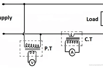
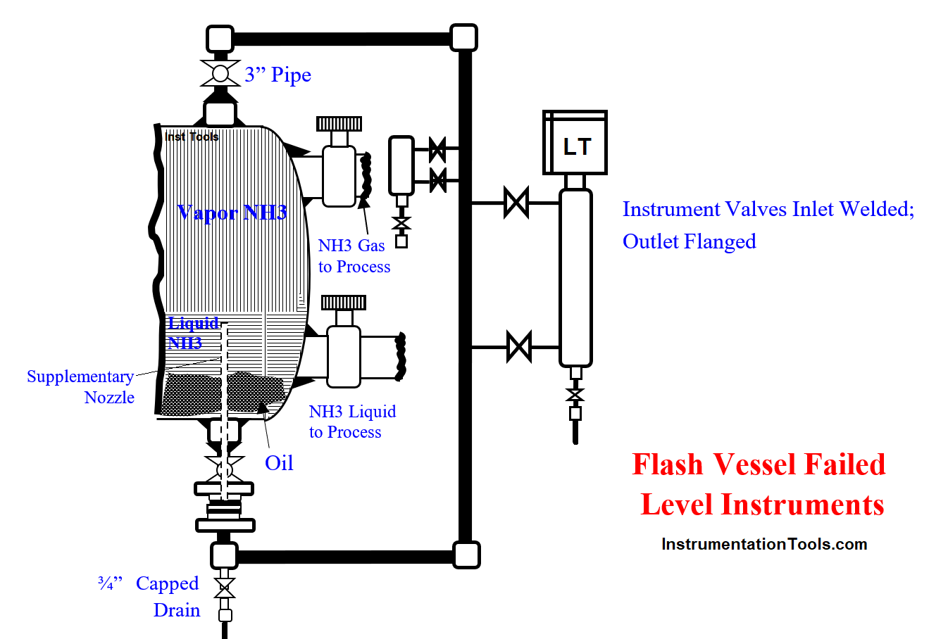
A Differential Level Transmitter (DLT), a Hi-Level (LG), a Lo-Level (LG), a Hi LS, a Hi-HI LS, a Lo LS, and a Lo-Lo LS – Seven level instruments – bolt to the 3” Sch 120 pipe connecting the vessel top nozzle (below figure; TN) to the bottom nozzle (BN).

The figure shows just two instruments to avoid clutter. Such instruments mounting avoids multiple taps welding on the 40‑bars operating pressure ammonia, N2, and H2 rich synthesis gas wetted vessel subjected to stringent weld codes.

Flash Vessel All Level Instruments Stopped Working

Flash Vessel Level Instruments Stopped Working

All the level instruments behaved erratic three months after commissioning.  Simultaneous erratic so many instruments behavior points blocked signals. Draining the line and steam cleaning if necessary seemed the answer.

All ridiculed the Author’s diagnosis, “how can liquid ammonia as clear as distilled water choke especially 3” pipe column feeding the instruments?” 

The author patiently explained, “Friends, I also don’t know the oil source; but oil draining only we can do. Let us do it and hope for the best. The 0.8 Sp Gr oil settles at the tank bottom below the 0.64 Sp Gr liquid NH3.

I guess this oil emulsified and choked the 3” pipe in 3 months. Hence, let us try oil draining. Though half-convinced, the crew were reluctant to drain fearing the extreme pungency of ammonia escaping to the atmosphere. Even PPM levels of ammonia are highly irritating.

Immediate Solution

The author guided the operation engineer to get the oil drained safely as under:

  1. Insert a hose clamped to the ¾” drain into an empty oil drum small dia hole and build a clay dam at the entry to avoid vapor leaks
  2. Screw in a 3 m long 1½” pipe to the large dia hole
  3. Close the bottom and top 3” block valves and open the ¾” drain valve and crack open the bottom 3” valve
  4. 40-bars gas pressure pushed tank bottom collected oil drains into the tank and the carried over and flashed gases escaping via the large 1½” pipe to the atmosphere well above the ground and winds carry these away
  5. After 15 minutes draining, close the ¾” drain valve, remove the hose clamped to the drain, crack open the ¾” drain valve; if oil drain continues clamp back the hose and continue draining few times as above till no oil comes out

Crew drained nearly ¾ drum of oil. Then they put the instruments back on service. Finally working all instruments cheered all.

The plant continued till the 18-months later turnaround by draining the oil two monthly.

Problem Solved Forever

The author got done below listed activities solved the problem forever:

  1. He got a supplementary nozzle made before the plant turnaround (TA). It is a 1.2 m long ¾” pipe welded to a 10 mm thick x dia = 3” 300 # RF flange dia
  2. Replaced the both sides welded 3” bottom valve with inlet welded and outlet flanged 3” gate valve.
  3. Inserted the supplementary nozzle into the tank and bolted back the 3” line

Thanks to the supplementary nozzle, oil did not reach the 3” pipe, and the instruments performed flawlessly between the two yearly TAs.

Operators conveniently drained the oil from the depressured tank easily and were extremely safe.

Intermediate & Final Solution Benefits

Intermediate & final Solution Benefits are:

  1. The intermediate solution enabled safe oil draining averted plant shutdowns for two monthly oil drains
  2. The final solution of inserting the supplementary nozzle eliminated the cumbersome and risky draining between turnarounds
  3. The level instruments perform will with conveniently draining the oil at a TA when the vessel is free of NH3 – very safe and easy task
  4. Always available reliable level readings smoothens plant operations and boosts safety.

Author: S. Raghava Chari

Do you face any similar issues? Share with us through the below comments section.

If you liked this article, then please subscribe to our YouTube Channel for Instrumentation, Electrical, PLC, and SCADA video tutorials.

You can also follow us on Facebook and Twitter to receive daily updates.

Read Next:

  • Level Transmitters Zero Drifts
  • Pitot-tube Replaced with Orifice
  • Mechanical Temperature Indicator
  • Pressure Transmitter Stopped Working
  • Seal Pressure Instruments Problems
Don't Miss Our Updates
Be the first to get exclusive content straight to your email.
We promise not to spam you. You can unsubscribe at any time.
Invalid email address
You've successfully subscribed !

Recommended Articles

Centrifugal Compressor Outage Reduced – Root Cause Analysis
Transformers Coolers Weld Joints Oil Oozes Were Eye Sores
Stuck Segment Orifice Dimensions Calculations
High-pressure Service Level Transmitters Misunderstood Zero Drifts
Seawater Pipeline Spools from day-1 leaks threaten Plant Shutdown
Cooling Tower fan FRP fan blades saves and saves
Share This Article
Facebook Whatsapp Whatsapp LinkedIn Copy Link
Share
Leave a Comment

Leave a Reply Cancel reply

Your email address will not be published. Required fields are marked *

Stay Connected

128.3kFollowersLike
69.1kFollowersFollow
208kSubscribersSubscribe
38kFollowersFollow

Categories

Recent Comments

  • William Snyder on Top Non-PLC Certification Courses for Automation Professionals
  • Kamli on Top Free PLC Software
  • Guifty Shimica on Top Non-PLC Certification Courses for Automation Professionals
  • Guifty Shimica on Top Non-PLC Certification Courses for Automation Professionals

Related Articles

Compressor IP Case Discharge Temperature Gradually Increases

Compressor Anti-Surge Control near-miss incident

Steam Letdown Station Problems

Steam Letdown Station Problems and their Solutions

Burst Transformers Root Cause Analysis

Root Cause Analysis – Burst Transformers and 11 kV Input Breakers

Pump Mechanical Seal and thrust bearing Problem

Pump 3-monthly Seal Leaks threaten entire Plant Shut down Indefinitely

Heat Exchanger Root Cause Analysis

Heat Exchanger Root Cause Analysis (RCA)

Sprocket Assembly and Bolting Segments

Bucket elevators Chain and teeth wear Problems

Poorly Built Switchgears

Poorly Built Switchgears – Why Breaker Parts Tear apart or don’t work?

Valve Actuator Passing

Lessons Learned from Actuator Passing Incidents

More Articles

DCS Alarm and Setpoint

Setpoints and Alarms in Control System

Nonlinear Control Systems

Stability of Nonlinear System – II

HMI

Learn about SCADA and HMI Systems

Single Phase Preventer Relay

Working Principle of Single Phase Preventer Relay

Power Electronics Objective Questions

Three Phase Rectifiers Questions and Answers

Centrifugal Compressor Start Permissive & Interlocks

Centrifugal Compressor Start Permissive and Interlocks

Ladder Logic of Motor Forward and Reverse

PLC Programming Example for Motor Forward and Reverse Control

Signal Isolator

What is a Signal Isolator? Principle, Advantages, Disadvantages

Follow US
All rights reserved. Reproduction in whole or in part without written permission is prohibited.
Welcome Back!

Sign in to your account

Username or Email Address
Password

Lost your password?