Inst ToolsInst ToolsInst Tools
  • Courses
  • Videos
  • Q & A
    • Interview
      • Instrumentation
      • Electronics
      • Electrical
      • Practical Questions
    • MCQ
      • Instrumentation MCQ
      • Electrical MCQ
      • Electronics MCQ
      • Control Systems MCQ
      • Analog Electronics MCQ
      • Digital Electronics MCQ
      • Power Electronics MCQ
      • Microprocessor MCQ
      • Multiple Choice Questions
  • EE
    • Electronics
      • Electronics Q & A
      • Electronic Basics
      • Electronic Devices & Circuits
      • Electronics Animation
      • Digital Electronics
    • Electrical
      • Electrical Basics
      • Electrical Q & A
      • Power Electronics
      • Electrical Machines
      • Electrical Animation
      • Power Systems
      • Switchgear & Protection
      • Transmission & Distribution
  • Measure
    • Control Valves
    • Calibration
    • Temperature
    • Pressure
    • Flow
    • Level
    • Analyzers
    • Switches
    • Vibration
    • Solenoid Valve
  • Control
    • PLC Tutorials
    • Control Systems
    • Safety Instrumented System (SIS)
    • Communication
    • Fire & Gas System
  • More
    • Design
    • Tools
    • Animation
    • Basics
    • Formulas
    • Standards
    • TextBooks
    • Common
    • Software
    • Excel Tools
    • Erection & Commissioning
    • Process Fundamentals
    • Videos
    • Books
Search
All rights reserved. Reproduction in whole or in part without written permission is prohibited.
Reading: Oval Gear Flow Meters – Principle, Advantages, Animation
Share
Notification Show More
Font ResizerAa
Inst ToolsInst Tools
Font ResizerAa
  • Courses
  • PLC Tutorials
  • Control Systems
Search
  • Courses
  • Videos
  • Q & A
    • Interview
    • MCQ
  • EE
    • Electronics
    • Electrical
  • Measure
    • Control Valves
    • Calibration
    • Temperature
    • Pressure
    • Flow
    • Level
    • Analyzers
    • Switches
    • Vibration
    • Solenoid Valve
  • Control
    • PLC Tutorials
    • Control Systems
    • Safety Instrumented System (SIS)
    • Communication
    • Fire & Gas System
  • More
    • Design
    • Tools
    • Animation
    • Basics
    • Formulas
    • Standards
    • TextBooks
    • Common
    • Software
    • Excel Tools
    • Erection & Commissioning
    • Process Fundamentals
    • Videos
    • Books
Follow US
All rights reserved. Reproduction in whole or in part without written permission is prohibited.
Inst Tools > Blog > Animation > Oval Gear Flow Meters – Principle, Advantages, Animation

Oval Gear Flow Meters – Principle, Advantages, Animation

Oval Gear Flow Meters are a type of positive displacement meter. As liquid flows through the meter, a pair of oval shaped gears are forced to rotate.

Last updated: October 31, 2023 4:22 pm
Editorial Staff
Animation Flow Measurement
No Comments
Share
3 Min Read
SHARE

Oval gear flow meters are a type of positive displacement meter. As liquid flows through the meter, a pair of oval-shaped gears are forced to rotate by the flow of the liquid.

Contents
Oval Gear Flow MetersPrinciples of OperationOVAL Gear Flow Meter AdvantagesOVAL Gear Flow Meter LimitationsApplications of OVAL Gear Flow Meters

These gears mesh together & force a finite amount of fluid through the meter.

Oval Gear Flow Meters

A sensor or mechanical drive detects the rotation of the gears to determine the displaced volume of liquid. The faster the flow rate, the faster the gears turn.
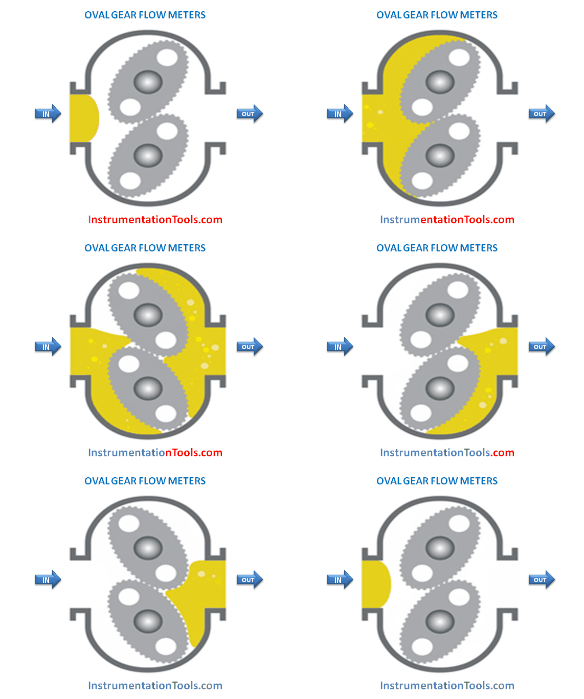
OVAL GEAR FLOW METERS WORKING ANIMATION

Principles of Operation

The oval gear flow meter comprises oval-shaped, geared rotors that rotate within a housing of specified geometry.

Fluid differential pressure causes the inter-meshing gears to rotate, trapping a ‘pocket’ of fluid between the gear and the outer housing and subsequently emptying the fluid pocket into the downstream flow. The capillary action of the metered fluid forms a liquid seal.

Each ‘pocket’ holds a precise and known volume of fluid so counting the pocket frequency gives a measurement of the volumetric flow rate. This is typically achieved by embedding magnets in the rotors, which then actuate a reed switch or provide a pulse output as they rotate and thus the flow is measured electronically.
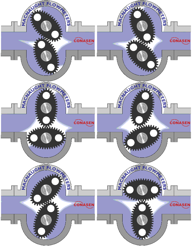
Oval gear Flow Meter Principle

OVAL Gear Flow Meter Advantages

  • Traditional proven flow technology
  • Simple to install
  • No straight pipe runs are required so flow meters can be installed in restricted areas

OVAL Gear Flow Meter Limitations

  • Not suitable for steam or multi-phase fluids
  • Fluid slippage adversely affects accuracy; this varies with flow rate, differential pressure, temperature, viscosity, and clearance
  • Not recommended for low-viscosity fluids, including water or water-like fluids (because of an increase in fluid slippage)
  • Accuracy is adversely affected by bubbles present in fluids

Applications of OVAL Gear Flow Meters

The oval gear flow meter is designed primarily for use with higher-viscosity fluids, which has led to applications such as the flow metering of oils, syrups, and fuels.

If you liked this article, then please subscribe to our YouTube Channel for Instrumentation, Electrical, PLC, and SCADA video tutorials.

You can also follow us on Facebook and Twitter to receive daily updates.

Read Next:

  • Ultrasonic Doppler Flow Meter
  • Positive Displacement meters
  • Microwave Flow Sensor Principle
  • DP Flow Transmitter Calculation
  • Metal tube Variable Area Meters
Don't Miss Our Updates
Be the first to get exclusive content straight to your email.
We promise not to spam you. You can unsubscribe at any time.
Invalid email address
You've successfully subscribed !

Continue Reading

Deluge System for Transformer Protection Animation
Rotary Abutment Flow Meters Working Principle and Animation
What is a Condensate Pot? How to Install it?
Displacer Level Sensor Working Animation
What is a Torbar? – Averaging Pitot Tubes
How Modbus is used in Industrial Networks?
Share This Article
Facebook Whatsapp Whatsapp LinkedIn Copy Link
Share
Leave a Comment

Leave a Reply Cancel reply

Your email address will not be published. Required fields are marked *

Stay Connected

128.3kFollowersLike
69.1kFollowersFollow
208kSubscribersSubscribe
38kFollowersFollow

Categories

Explore More

Phase Watcher Multiphase Flow Meter (MPFM) Procedure
Sounding Level Transmitter Working Animation
Cat and Mouse type Level Indicator
Why is Orifice Beta in between 0.3 to 0.7?
Resistor Color Code Animation
Orifice Plate Turndown ratio
Is it Easy to Measure Natural Gas Flow and Volume?
Ultrasonic Level Transmitter Animation
Flow Meter K-factor and Calculations
Types of Flow Meters MCQ – Instrumentation and Control

Keep Learning

Online Simulation

types of Orifice Plates

Types of Orifice Plates & Orifice Plate Tappings

Hot wire Anemometer Principle

Hot Wire Anemometer Principle and Types

Turbine Meter Custody Transfer

What is Gas Meter and Regulating Station?

Orifice Construction

How does an Orifice Measures Flow?

Coriolis Mass Flowmeter Principle

Coriolis Mass Flow Sensor Theory

Coriolis Mass Flow Meter Verification Procedure

Prover Tank Calibration and Mass Flow Meter Verification Procedure

Square-Root extraction in DCS or Transmitter

Square-Root in DCS or Flow Transmitter?

Discover More

Level Gauge Interface Measurement

Level Gauge Interface & Temperature Problems

Active Barrier

What is a Active Barrier ?

Pressure Gauges with Diaphragm Sensor Principle

Pressure Gauges with Diaphragm Sensor Principle

Selection Guidelines for Cable Glands

Selection Guidelines for Cable Glands

Insulation Resistance Test

What is an Insulation Resistance Test? – Types, Applications

Digital Electronics Multiple Choice Questions

Demultiplexers Objective Questions

Computer Networks Multiple Choice Questions

150 Computer Networks Multiple Choice Questions and Answers

Integral Control Principle

Integral Controller Principle

Follow US
All rights reserved. Reproduction in whole or in part without written permission is prohibited.
Welcome Back!

Sign in to your account

Username or Email Address
Password

Lost your password?