Inst ToolsInst ToolsInst Tools
  • Courses
  • Automation
    • PLC
    • Control System
    • Safety System
    • Communication
    • Fire & Gas System
  • Instrumentation
    • Design
    • Pressure
    • Temperature
    • Flow
    • Level
    • Vibration
    • Analyzer
    • Control Valve
    • Switch
    • Calibration
    • Erection & Commissioning
  • Interview
    • Instrumentation
    • Electrical
    • Electronics
    • Practical
  • Q&A
    • Instrumentation
    • Control System
    • Electrical
    • Electronics
    • Analog Electronics
    • Digital Electronics
    • Power Electronics
    • Microprocessor
  • Request
Search
  • Books
  • Software
  • Projects
  • Process
  • Tools
  • Basics
  • Formula
  • Power Plant
  • Root Cause Analysis
  • Electrical Basics
  • Animation
  • Standards
  • 4-20 mA Course
  • Siemens PLC Course
Reading: How to Delay a Sensor Signal in PLC?
Share
Notification Show More
Font ResizerAa
Inst ToolsInst Tools
Font ResizerAa
  • Courses
  • Design
  • PLC
  • Interview
  • Control System
Search
  • Courses
  • Automation
    • PLC
    • Control System
    • Safety System
    • Communication
    • Fire & Gas System
  • Instrumentation
    • Design
    • Pressure
    • Temperature
    • Flow
    • Level
    • Vibration
    • Analyzer
    • Control Valve
    • Switch
    • Calibration
    • Erection & Commissioning
  • Interview
    • Instrumentation
    • Electrical
    • Electronics
    • Practical
  • Q&A
    • Instrumentation
    • Control System
    • Electrical
    • Electronics
    • Analog Electronics
    • Digital Electronics
    • Power Electronics
    • Microprocessor
  • Request
Follow US
All rights reserved. Reproduction in whole or in part without written permission is prohibited.
Inst Tools > Blog > PLC Tutorials > How to Delay a Sensor Signal in PLC?

How to Delay a Sensor Signal in PLC?

Learn how to delay a sensor signal in the PLC function block programming with the help of on-delay timer code.

Last updated: September 28, 2022 2:24 pm
Hussien Ghareb
PLC Tutorials
No Comments
Share
4 Min Read
SHARE

First of all, and before we getting into our code, we should know:

Contents
Why do we need to Delay a Sensor Signal?ExampleNow It’s PLC Coding TimeDownload the Logic

Why do we need to Delay a Sensor Signal?

As an operator one of the best features of your plant or process is the speedy response of your system (level sensors, pressure switches, actuators ….) that would really help you to control and monitor your plant easily, but as all of us know

“There is no fixed rule in our life”, there would be some other situations that really need the signal of some sensors in the plant to be delayed, look for the next alternative situation.

Example

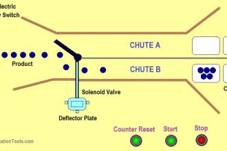
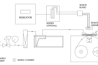
We have a storage tank in our process that maintain a certain level of (seeds, water, oil ….), this tank has a high-level switch.

When this level is on the whole process would start, for some reasons (some of the seeds touch the sensor when you fill up the silo) you may found the level sensor has a deceptive signal for just 100msec and this could happen several times. Such a problem would really make some Significant losses to your system.

So, here is the simple solution with just 2 or may 3 second delay for the level signal you will ensure that is the real signal of the switch and your silo is definitely is full.

NOTE do not make a long delay as that could make another issue and negative effects with the process.

Now It’s PLC Coding Time

Our code is built using just function as there is no need to use a function block.

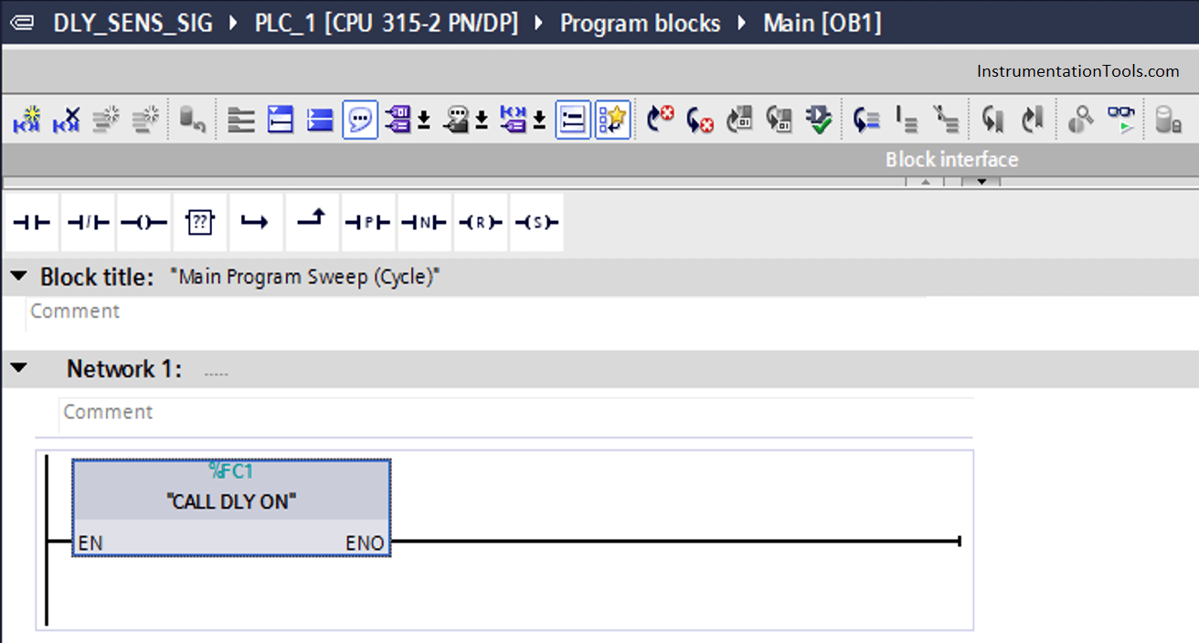
First of all, we are calling the function that is responsible for delaying the desired sensors from the main OB (Organization Block).

As said before, the structure and organization of the code is a very critical point that you should be aware of.

How to Delay a Sensor Signal in PLC

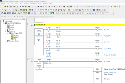
Now we are in the function (FC1) that contains the blocks that control the sensor signals.

The first Network is a timer that responsible for initializing a pulse every one second.

The other networks contain the function that responsible for delaying the sensor signal (FC2)

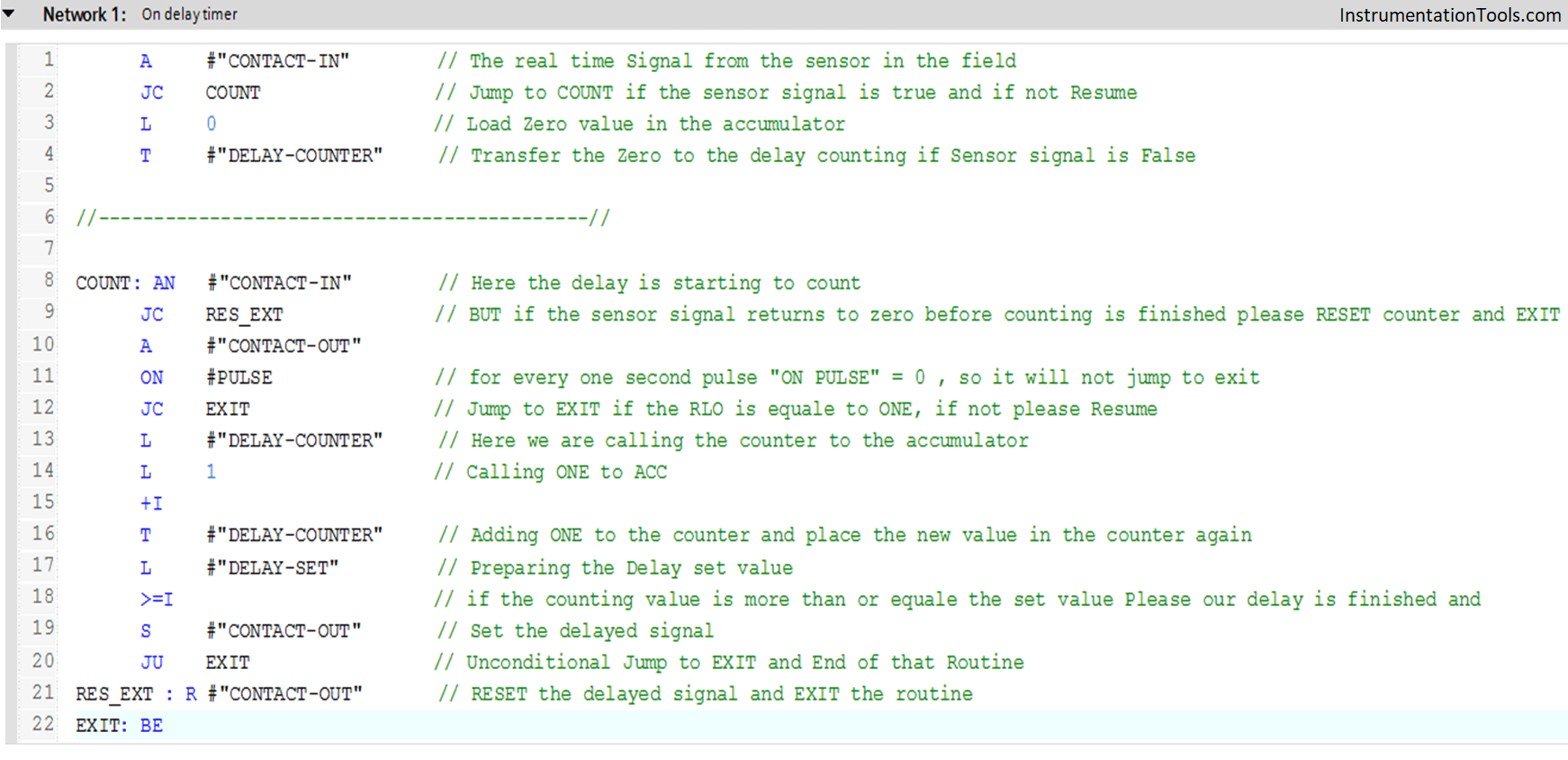
  • “ONDLY-TMR” is the function
  • CONTACT-IN – It is the real-time sensor signal getting from the field.
  • PULSE – it’s a one-second pulse from the first network that makes the delay between counts.
  • DELAY-SET – It is the No. of set counts (this set is converted to seconds).
  • DELAY-COUNTER – It is the counter that will be compared with the set value
  • CONTACT-OUT – It is the delayed signal that you can put on Marker or Data Block to reuse it.
On Delay Timer in Siemens PLC

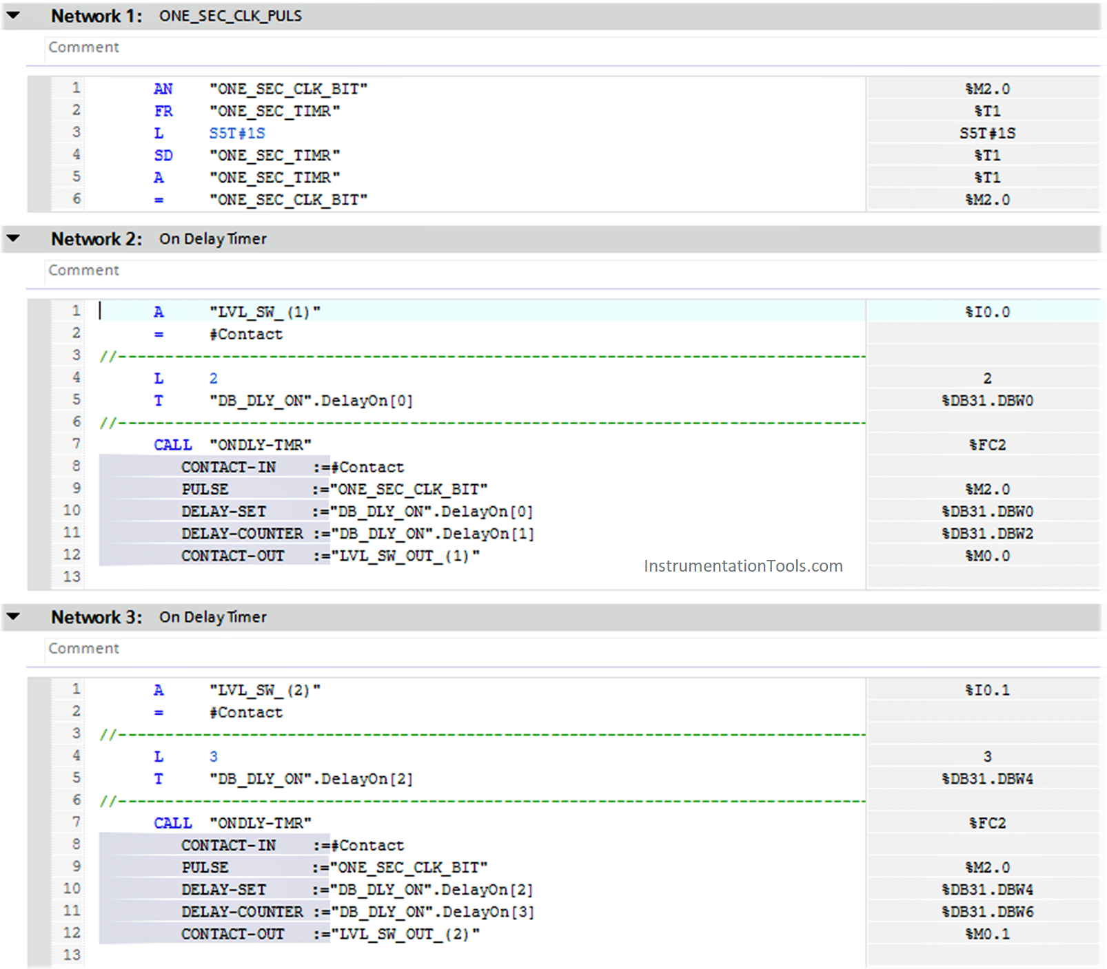
Here we have our Logic that handles the desired function with some comments to make it easy to understand…

PLC Timer Code

Download the Logic

  1. CALL DLY ON (FC1)
  2. ONDLY-TMR (FC2)

Code Made By Sachen

If you liked this article, then please subscribe to our YouTube Channel for PLC and SCADA video tutorials.

You can also follow us on Facebook and Twitter to receive daily updates.

Read Next:

  • PLC Practice Questions
  • Basics of Ladder Diagram
  • Electrical Circuit Schematic
  • How to Choose Right Fuse?
  • PLC Trainer Demo Download
Don't Miss Our Updates
Be the first to get exclusive content straight to your email.
We promise not to spam you. You can unsubscribe at any time.
Invalid email address
You've successfully subscribed !

Continue Reading

Communication Processor Module in Siemens PLC
Single-acting Cylinder OR Logic Operation (PLC and Sensors)
Types of CPU Communication Ports in Siemens PLC
Daily Alarm PLC Program using Real-Time Clock
What is Resources Tab in the Siemens PLC?
PLC Hoist Crane Programming: Example using Schneider
Share This Article
Facebook Whatsapp Whatsapp LinkedIn Copy Link
Share
Leave a Comment

Leave a Reply Cancel reply

Your email address will not be published. Required fields are marked *

Stay Connected

128.3kFollowersLike
69.1kFollowersFollow
210kSubscribersSubscribe
38kFollowersFollow

Categories

Explore More

PID Simulator Download
Difference between DCS & PLC Systems
PLC Program for Bank Counter Application
Single-acting Pneumatic Cylinder Operation with Limit Switch
Batch Mixing with PLC Ladder Logic Program
How to Protect Siemens PLC using Password?
PLC Logic GATE Program
What is PCS 7?

Keep Learning

Electrical Drives Animation

Electrical Drives – Modes, Types, Speed Control Applications

Siemens PLC

Will PLCs become obsolete?

PLC Program Example - Signal Lamp Task

PLC Program Examples

Simatic Prosave HMI

How to Backup and Restore from Simatic Prosave HMI?

DeMorgan's Theorems

DeMorgan’s Theorems using Ladder Diagram

PLC Cabinet

PLC Programming Videos

Automatic Car Door Simulation

Automatic Door Operation PLC Programming and Simulation

Two Hand Control Logic

Two Hand Control Logic using PLC

Learn More

Steam Tracing

Steam Tracing

stepper motors Animation

Fundamentals of DC Motor Animation

What is SMPS

What is SMPS? – Types of SMPS

Fundamentals of Digital Systems Quiz

200 Quiz Questions on Fundamentals of Digital Systems

Temperature Calibration Bath

Temperature Calibration Bath Principle

Series Air Fuel Combustion Control

Combustion Control – Series and Parallel Air-Fuel Ratio Control

How to Activate the Schneider PLC Software License

How to Download EcoStruxure Machine Expert? Schneider PLC Software

Mechanical Strainers

Strainers

Menu

  • About
  • Privacy Policy
  • Copyright

Quick Links

  • Learn PLC
  • Helping Hand
  • Part Time Job

YouTube Subscribe

Follow US
All rights reserved. Reproduction in whole or in part without written permission is prohibited.
Welcome Back!

Sign in to your account

Username or Email Address
Password

Lost your password?