In the present times, Smart transmitters are widely used in process industries. However, ordinary transmitters still exist in various industries, its application is confined to non-critical and applications of less importance.
This article analyses the difference between the ordinary transmitter and smart transmitter taking pressure, differential pressure transmitter, and temperature into consideration.
Ordinary Transmitter
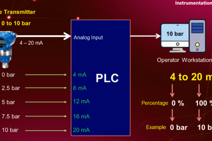
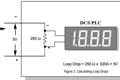
- Ordinary pressure transmitters give a 4-20 mA signal output on a two-wire connection, corresponding to 0-100% of the measured variable range, they have limited adjustability for different pressure ranges.
- Performance varies with parameters such as temperature changes, time, and static pressure variations.
- A schedule for recalibration is needed to maintain acceptable performance.
- This recalibration procedure is time-consuming and difficult to carry out in an open environment with, usually, hazardous conditions.
Smart Transmitter
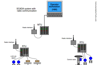
- The smart transmitters can be a replacement for ordinary transmitters and are connected via ordinary two-wire 4-20 mA wiring but with the added capability of digital communication from a smart hand-held interface (SFC) connected anywhere the 4-20 mA is accessible.
- Smart transmitters are capable of working with wide varieties of thermocouple, and RTD elements.
- Smart transmitters enable remote adjustment of the transmitter database.
- With smart transmitters obtaining diagnostic information to minimize loop downtime.
- The significance of smart the transmitter concept provides vastly improved performance and rangeability.
- Digital electronics has enabled a quantum push forward in performance and benefits.
Differences
Key differences between ordinary transmitter and smart transmitter:
- Performance
- Rangeability
- Remote Adjustability
- Reliability.
Performance
The major improvements of smart transmitter’s accuracy, static pressure effects, temperature performance, and time stability give an overall improvement in the performance.
Rangeability
Rangeability is increased to 400: 1 for the smart transmitter against the ordinary transmitter from 6:1.
Significantly extended rangeability helps to
- Reduce costs of spare management,
- Increase the interchangeability of smart transmitters with plant alterations, and
- Provides other benefits such as freedom from having to define exact ranges when ordering units.
A clear example of real savings through increased rangeability is in applications where two or more conventional units are applied across a single orifice plate to improve accuracy over a wide range of flows.
The increased rangeability of the smart transmitter means that only one unit is required, thereby saving not only the other units and the cost of installing and maintaining them and also preventing the inherent low reliability of two or three loops against one.
In the case of the smart transmitter, the range can be changed manually through the communicator for different plant operating conditions.
Remote Adjustability
The smart transmitter range, damping, etc., can now be adjusted from up to 1500 m away by communication over the 4-20 mA signal line.
The adjustment can be done by connecting a smart field communicator (SFC) across the two signal lines at any point along their path.
- The output may be characterized as the linear or square root
- Damping time constant may be adjusted in several steps
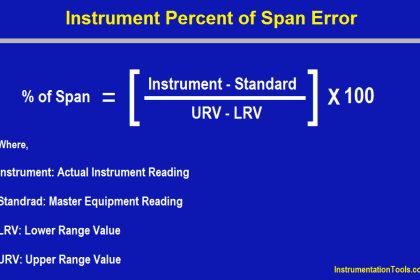
- LRV/URV may be adjusted to any value in the pressure range.
Adjustments are made in any engineering units selectable from PSI, m bar, bar, k Pa.
The re-ranging of the smart transmitter without applying pressure is possible.
Calibration corrections can be made for small errors caused by mounting angle effects.
Zero checks, and corrections if necessary, can be performed from the control room at plant shut-downs or during normal maintenance.
Rearranging and remote diagnostics can now be performed back at the control room, thus taking a fraction of the previous maintenance time which usually requires two men for several hours to do any field check or change.
All of the above can be carried out by one man from the convenience of the central location.
Reliability
The main aim of smart transmitters has been designed with reliable and stable operation as the dominant requirement.
A few components are used, and protection is provided against damaging influences, such as reverse polarity, over-pressure, and surge voltage.
The smart transmitters also have been designed to meet Cenelec Intrinsic Safety and Explosion-proof Standards as well as other International Safety Approval requirements.
The enclosure complies with classification IP67 which prevents moisture, dust ingress problems with the working of the transmitter.
In the smart transmitter, since they do not contain switches, links, or any type of adjustments in the electronics compartment, the integrity transmitter enclosure need not be disturbed, and the likelihood of a transmitter cap being left loose is greatly reduced.
Diagnostic aids are included in both transmitters and SFC to avoid misuse, e.g. by identifying excessive process temperature or, in the event of a component breakdown, to identify the fault, advise the SFC operator and alert the control room by giving an upscale alarm signal.
In the event of a transmitter or loop problem, the diagnosis via the SFC from the control room area will identify the problem and corrective action by the maintenance team can be carried out. Loop downtime is minimized.
Read Next: