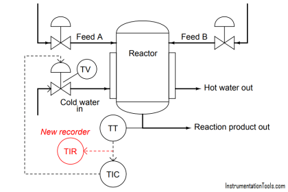
Calculate the 0%, 50%, and 100% calibration points for the DP transmitter to measure liquid level in this vessel, given a range of 0 to 30 feet and a process specific gravity of 0.85.
Note the “wet” leg filled with fluid different than the process (SG = 1.1), 35 feet tall:
In this example, the transmitter output loop current range is 10 to 50 mA.
DP transmitter Calibration Points
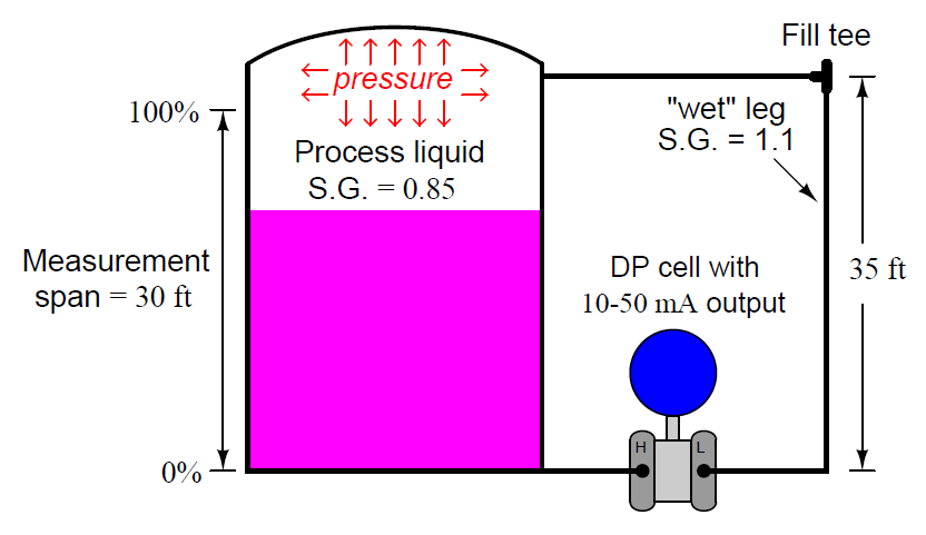
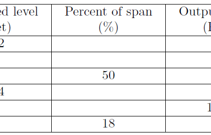
Calculate the equivalent ΔP range (inch H2O) and loop current (mA) for 0%, 50%, and 100% of process variable.
Answer:
ΔP range (inch H2O)
0% = -462
50% = -309
100% = -156
Loop Current (mA)
0% = 10
50% = 30
100% = 50
Share your answers and explanation with us through the below comments section.
Read Next:
- Purge Level Transmitter
- DP transmitter Calibration
- Hydrostatic Pressure
- Types of Limit Switches
- Piping and Fittings
Credits: Tony R. Kuphaldt