The orifice is normally used for flow measurement of liquid, gas, and steam. The orifice produces differential pressure (DP) across the plate and it is sensed by DP type transmitter. This Differential pressure then square rooted to convert into the equivalent flow.
Square rooting can be done either at DP type flow transmitter side or at the control system side. Flow output is valid when we operate the plant at the specified operating conditions as per flow element sizing calculation.
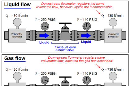
In the industry, practically, these parameters like design temperature and design pressure cannot be maintained throughout the operation. Once the pressure/temp varies, density will be affected due to which Volume will change and the DP transmitter cannot detect the density changes.
The volumes of gas/steam measured are highly affected by pressure and temperature. This is when we require pressure, temperature compensation where in actual operating conditions will be used.
Flow Measurement
This type of compensation is applicable when we have DP type flow elements like Orifice, venturi, pitot tube, etc, and Gas or Steam as a service application. Pressure and temperature (PT) compensation convert a volumetric gas flow at specific conditions into an equivalent volumetric flow at base conditions.
Commonly, density measurement is not used, another approach is to measure Molecular weight (online/offline) and then compensate with design molecular weight.
PT (P&T) compensation is a complete makeover of the traditional orifice. This produces a resultant value for flow that is more accurate because it is compensated for the error effects of the other variables at the operating conditions.
The PT calculations are based on absolute temperature and pressure.
Pressure Temperature Compensation
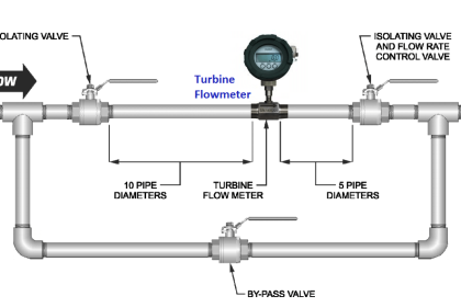
The complete arrangement will look as per the following P&ID figure.
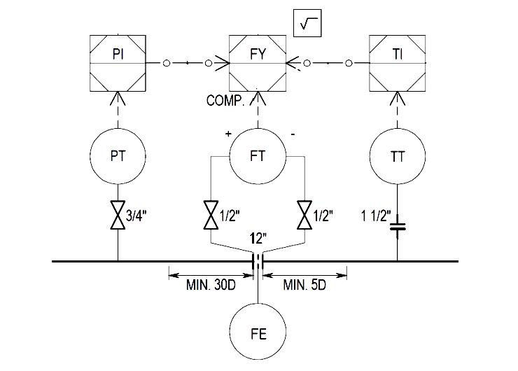
In general, the pressure transmitter installed at the upstream side of the flow element, and the temperature transmitter installed downstream so that it does not distort the velocity profile in the flow element.
Nowadays, a Multi-variable transmitter is commonly used to avoid such an above arrangement which has compete DP, Pressure, and/ Temperature measurement as part of the transmitter itself. There are options available in Multi-variable transmitters like separate RTD / Thermocouple for temperature measurement.
Vortex transmitter is also available with integrated Pressure and/ temperature compensation which can be suitable to use in the Steam / Gas application.
Various examples are simulated in Conval sizing software to get better clarity. Pressure and temperature changes are simulated and compensated outputs are compared. This is to know how PT compensation really matters !!
Example Calculations
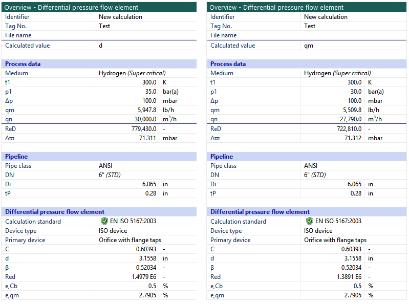
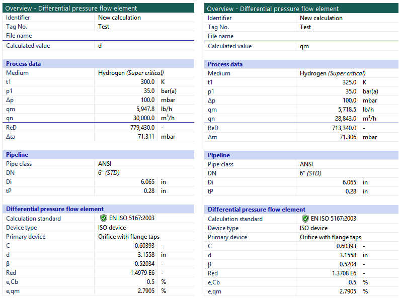
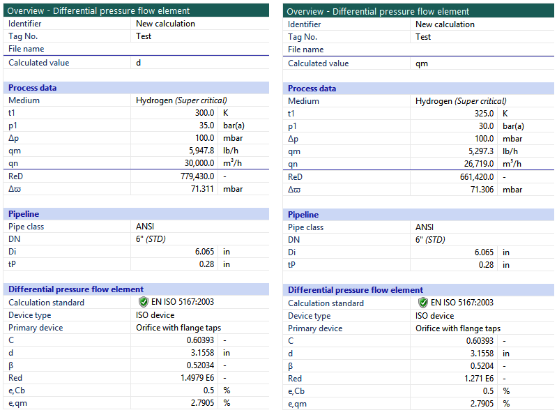
Let’s take an example of H2 Gas where in Orifice is calibrated/designed for DP of 100 mBar, Input Pressure 35 Bara, Input Temp 300 K, Flow is 30,000 m3/hr, where orifice Beta ratio found from Conval Software output is 0.52034.
Now, we take reverse calculation, keeping the orifice bore fixed, and change the input pressure from 35 Bara to 30 Bara. The flow output calculated is 27,790 m3/hr. Assume that density measurement is not available.
Resultant compensated flow due to change in pressure can be derived by the following equation
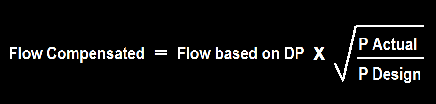
Flow Compensated = = 30,000 *SQRT(30/35) = ~ 27,774 m 3 /hr
Hence, for this example 5 Bara reduction in pressure w.r.t. to design condition, resulted in 7.3% less flow (when you have pressure compensation in place.)
Lets now look at what happens when temperature changes from 300 K to 325 K keeping other parameters the same as design. The flow output calculated is 28843 m3/hr.
Resultant compensated flow due to change in temperature can be derived by the following equation
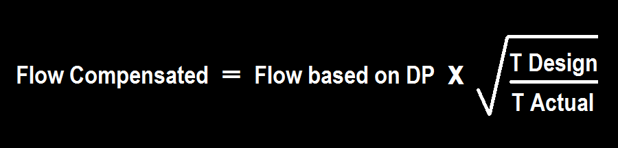
Flow Compensated = 30,000 * SQRT(300/325) =~ 28,823 m3/hr
Hence, for this example, a 25 K increase in temperature resulted in a 3.8% less flow.
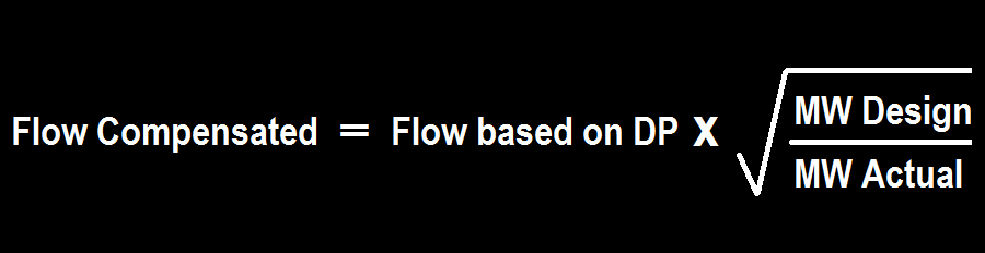
In this example, If we take temperature and pressure change together w.r.t design condition, then flow output is 26,719 m3/hr
Resultant compensated flow due to change in pressure and temperature can be derived by the following equation

Flow Compensated = 30,000 * SQRT((30*300/(35*325)) = ~ 26,684 m3/hr
Since Conval software calculates the exact properties of H2 gas based on the operating conditions so there is a difference in flow output calculated by Conval and equation. However, the equation mentioned is valid to implement.
Similarly, if we have a molecular weight (MW) changes w.r.t design then Flow compensated can be calculated as per the below equation.
Altogether, the flow compensated can be calculated with actual temperature, actual pressure, and actual molecular weight, etc.
Molecular weight can be known from Lab analysis or online analyzer.
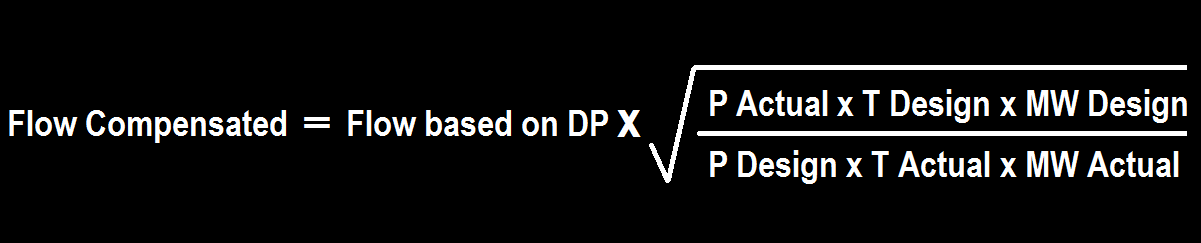
Pressure values shall be in Bar(a), Temp shall be in K.
Flow-based on DP = flow calculated from square rooted actual DP reading
All the design inputs/ reference conditions can be known from the flow element sizing sheet. Actual parameters will be part of the analog input signal to the control system.
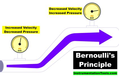
The equation shown above is derived from Euler’s equation of continuity and Bernoulli’s principle. Derivation of this formula is out of the scope of this article.
It is very much important to pass-on correct flow compensation equation based on process requirement (Pressure compensation/ Temperature compensation / P&T compensation / P, T & MW Compensation) along with your design parameter and ranges to control system vendor to have this flow compensation calculation implemented inside the PLC/ DCS.
Some control system supplier has flow compensation blocks into their library. However, verification of compensated flow output is necessary.
Exercise for you
Design Pressure 40 Bar(a), Design Temp 375K, Calibrated Flow range 0-5000 Kg/hr, DP type flow transmitter is calibrated at 0-2500 mmH2O.
When your field pressure transmitter reading is 35 Bar(a), Temp transmitter reading is 340K, and DP FT reads 1250 mmH2O then what will be P&T compensated flow output?
The correct answer is 3473.06 Kg/hr.
Please let us know in the comment box if you find difficulty in solving it.
If you liked this article, then please subscribe to our YouTube Channel for Instrumentation, Electrical, PLC, and SCADA video tutorials.
You can also follow us on Facebook and Twitter to receive daily updates.
Read Next:
- Orifice Drain and Vent Hole
- Facts about Orifice Plates
- Orifice Meter Specifications
- Transmitter Calibration Frequency
- Instrumentation and Control Quiz


can you please explain, how you got 3473.06 kg/hr?
I got it wrong
Flow is proportional to square root of DP.
50% DP is not equal to 50% of flowrate.
Flow1 => sqrt(DP1)
Flow2 => sqrt(DP2)
Flow1 = 5000 kg/hr
DP1 = 2500 mmH2O
DP2 = 1250 mmH2O
Find out flow 2 and then multiply with Pressure and temperature factor.
I got it wrong. Please explain the calculation.
can u explain
Can you explain ? What I calculated is 2455.95kg/hr
Flow based on DP is 2500kg/hr and Temp.&Press. compensation value is 0.95
Hello,
I think there might be an error in the formula you use for the pressure and temperature changes: the way you wrote the equation gives a mass flow imo, it should be more like
” sqrt( (Pdesign * Tactual) / (Pactual * Tdesign) ) ”
What do you think about this?
Regards
I agree, I have been wrapping my head around this and wanted to check my reasoning online, only to find these calculations which I think are inversed.
Hi again.
Kindly change the answer for this question below
Which of the following represents normal value for Pin/Pout?
Answer : 0.2 and 0.75 (as per explanation)
I think formula is wrong for molecular weight sqrt (MW actual/MW design). Please confirm
Given are the Calibrated Range for a certain DP range & the trick is when you have only half of the estimated DP.
5000 = K * Sqrt(2500)
5000 = K * 50
K = 100
Now
Flow Calculated = K * Sqrt(1250) = 100 * 35.356 = 3535.539
3535.539 * (Sqrt (35 * 375)/(40 * 340) )
= 3473.243 Kg/hr
Can this formula be used with natural gas?
Thank you. very good explanation
Required temperature Pressure Compensation unit
hi there
first i would like to thank you for your explanation
however i just want to understand from where do you get your design parameters ???
is it the parameters the orifice plate is designed for ?
for example if i want to change the orifice with another one that has different parameters do i need to change the design (pressure and temperature ) for the new orifice ?
If we have gas volumetric flow at Normal conditions in Nm3/h in the compensation formula the design/calibration Pref & T ref will be P&T at Normal conditions: P-1atm and T=0C?
Hi if we need to extend the measurement range with the existing orifice plate.
But the normal operating pressure and temperature has been changed.
In calculation pressure design and temp design, should we change according to the new operating condition?