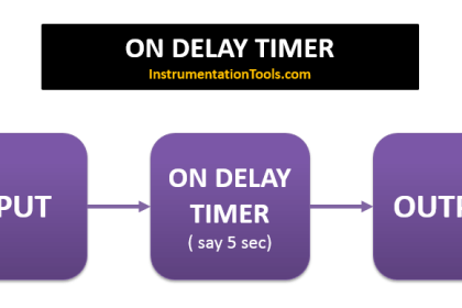
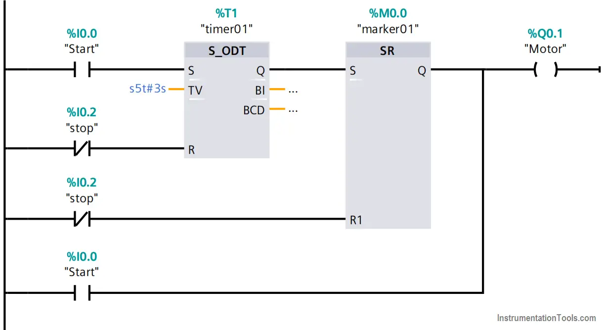
Write a PLC program that when a start push button (PB) is pressed the motor runs and when released the motor stopped. And if the PB is pressed for more than 3 seconds the motor runs in the latched mode until the stop PB is pressed.
Note the best practice to learn the PLC programming is to start writing the PLC program, take your time before you review the answer.
Inputs & outputs:
I0.0: Start Push Button (Normally open contact)
I0.2: Stop Push Button (Normally closed contact)
Q0.0: Motor
M0.0: marker 01
T1: timer 01
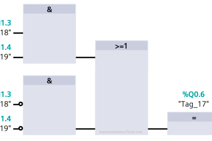
Push button Motor PLC Logic
PLC Program description
When the start PB is pressed for less than 3 seconds, the last branch in the network would energize the motor as long as the PB is pressed.
When the start PB is pressed for more than 3 seconds, the timer T1 would be energized and send a pulse signal to the SR flip flop which would energize the motor in a latched mode.
Whenever the stop PB is pressed, the motor would stop.
Author: Karim Ali Anwar
If you liked this article, then please subscribe to our YouTube Channel for PLC and SCADA video tutorials.
You can also follow us on Facebook and Twitter to receive daily updates.
Read Next:
- Siemens PCS 7
- InTouch Scada Password
- Allen Bradley FIFO Instruction
- PLC Alarm Acknowledge
- Motor Stop Interlock