Inst ToolsInst ToolsInst Tools
  • Courses
  • Videos
  • Q & A
    • Interview
      • Instrumentation
      • Electronics
      • Electrical
      • Practical Questions
    • MCQ
      • Instrumentation MCQ
      • Electrical MCQ
      • Electronics MCQ
      • Control Systems MCQ
      • Analog Electronics MCQ
      • Digital Electronics MCQ
      • Power Electronics MCQ
      • Microprocessor MCQ
      • Multiple Choice Questions
  • EE
    • Electronics
      • Electronics Q & A
      • Electronic Basics
      • Electronic Devices & Circuits
      • Electronics Animation
      • Digital Electronics
    • Electrical
      • Electrical Basics
      • Electrical Q & A
      • Power Electronics
      • Electrical Machines
      • Electrical Animation
      • Power Systems
      • Switchgear & Protection
      • Transmission & Distribution
  • Measure
    • Control Valves
    • Calibration
    • Temperature
    • Pressure
    • Flow
    • Level
    • Analyzers
    • Switches
    • Vibration
    • Solenoid Valve
  • Control
    • PLC Tutorials
    • Control Systems
    • Safety Instrumented System (SIS)
    • Communication
    • Fire & Gas System
  • More
    • Design
    • Tools
    • Animation
    • Basics
    • Formulas
    • Standards
    • TextBooks
    • Common
    • Software
    • Excel Tools
    • Erection & Commissioning
    • Process Fundamentals
    • Videos
    • Books
Search
All rights reserved. Reproduction in whole or in part without written permission is prohibited.
Reading: Cascade Temperature Control System
Share
Notification Show More
Font ResizerAa
Inst ToolsInst Tools
Font ResizerAa
  • Courses
  • PLC Tutorials
  • Control Systems
Search
  • Courses
  • Videos
  • Q & A
    • Interview
    • MCQ
  • EE
    • Electronics
    • Electrical
  • Measure
    • Control Valves
    • Calibration
    • Temperature
    • Pressure
    • Flow
    • Level
    • Analyzers
    • Switches
    • Vibration
    • Solenoid Valve
  • Control
    • PLC Tutorials
    • Control Systems
    • Safety Instrumented System (SIS)
    • Communication
    • Fire & Gas System
  • More
    • Design
    • Tools
    • Animation
    • Basics
    • Formulas
    • Standards
    • TextBooks
    • Common
    • Software
    • Excel Tools
    • Erection & Commissioning
    • Process Fundamentals
    • Videos
    • Books
Follow US
All rights reserved. Reproduction in whole or in part without written permission is prohibited.
Inst Tools > Blog > Control Systems > Cascade Temperature Control System

Cascade Temperature Control System

Last updated: March 28, 2020 11:54 am
Editorial Staff
Control Systems
No Comments
Share
4 Min Read
SHARE

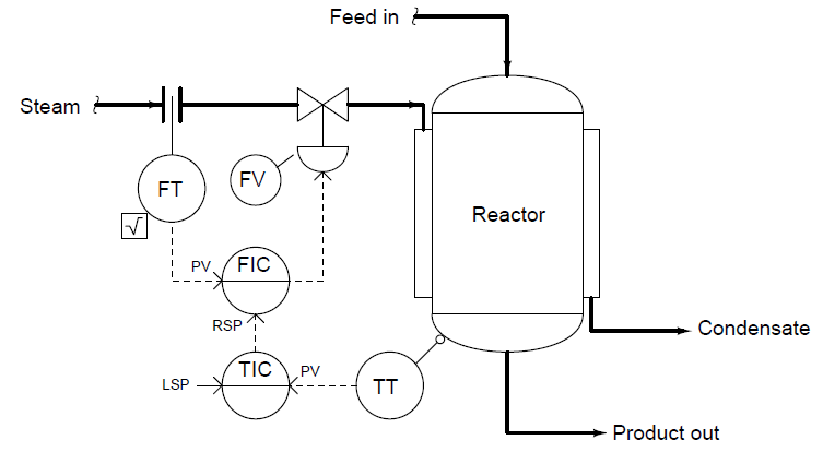
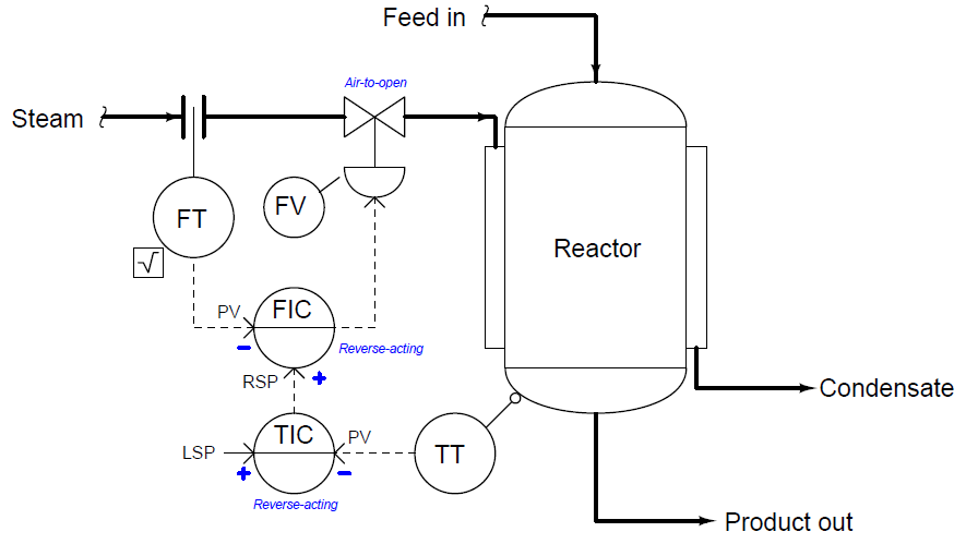
Explain the operation of this cascade temperature control system:

Contents
Cascade Temperature Control SystemAnswer:Questions for you:Read Next:

Cascade Temperature Control System

Cascade Temperature Control System

Cascade control systems (also called two-element control systems) have two control “loops” functioning: a master and a slave (also known as primary and secondary, respectively). Identify the master (primary) and slave (secondary) loops in this temperature control system, and also determine which loop should be tuned first (and why!).

Also, identify the appropriate controller actions for each loop, assuming direct-acting transmitters and an air-to-open valve. Annotate this diagram with “+” and “−” symbols showing the influences PV and SP have on each controller, and explain how these symbols help your analysis of the controllers’ actions.

Answer:

The temperature controller (TC) provides a “remote” setpoint to the flow controller (FC), which throttles the flow control valve (FV) to achieve the desired rate of steam flow.

Master (primary) = Reactor temperature

Slave (secondary) = Steam flow

When tuning cascaded loops, you should always ensure the slave loop is well-tuned before attempting to tune the master loop. I’ll let you figure out why this is important!

Temperature Control Loop


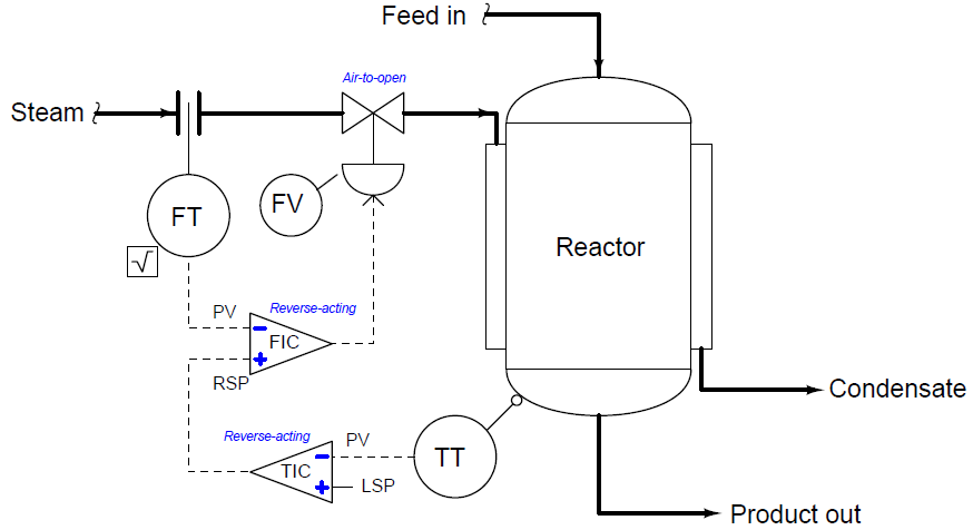
A useful problem-solving strategy for determining necessary controller actions in a cascade control system is to replace the ISA-standard “bubble” symbols for controllers with triangular opamp symbols, complete with “+” and “−” symbols at the inputs.

One input of each “opamp” controller will be the PV, while the other input of each “opamp” controller will be the SP. The inverting and noninverting inputs standard to all operational amplifiers helps remind you that the PV and SP inputs of a loop controller always have opposite effects on the output signal.

So a helpful strategy for identifying necessary master and slave controller actions in a cascade control system is to re-draw the controller “bubbles” as opamp symbols instead, complete with “+” and “−” labels for noninverting and inverting inputs, respectively.

Since all PID controllers have PV and SP inputs, and these inputs always have opposite effects on the output signal, the opamp conventions of “+” and “−” work very well to describe the action of any PID controller. If the PV input on the opamp controller must be noninverting (“+”) in order to achieve loop stability, then that controller must be direct-acting.

If the PV input on the opamp controller must be inverting (“−”) in order to achieve loop stability, then that controller must be reverse-acting.

The following diagram shows how to use opamp symbols to represent controller actions in the same cascaded flow/temperature control system:

Reverse Acting Control Loop

Note that it is always the inputs of a controller we label with “+” or “−” symbols, never the output of a controller.

Questions for you:

When tuning each loop controller (TIC, FIC), what should be done with the other controller? Should the other controller be in automatic mode or manual mode, and why?

Suppose the control valve were switched from air-to-open to air-to-close. Would both master and slave controller actions need to be reversed, or just one of the controllers? If just one, which one?

Identify any load(s) on this process that are not being corrected or otherwise compensated for by cascade control.

Share Your Answers with us through comments.

Read Next:

  • Control Valve Split Range Loop
  • Industrial Automation and Control
  • PID Controllers Graphical Analysis
  • Security of Automation Systems
  • Pressure Control Problems

Credits: Tony R. Kuphaldt
Don't Miss Our Updates
Be the first to get exclusive content straight to your email.
We promise not to spam you. You can unsubscribe at any time.
Invalid email address
You've successfully subscribed !

Recommended Articles

Alarm Simulator for Annunciator Logic
Open Platform Communication (OPC)
Basics of Trips, Interlocks, Permissives & Sequences
How does a Redundant Controller comes in line when the Main Controller fails?
How to Analyze PID Controller Actions
Why Baud Rate is Important in Modbus Network?
Share This Article
Facebook Whatsapp Whatsapp LinkedIn Copy Link
Share
Leave a Comment

Leave a Reply Cancel reply

Your email address will not be published. Required fields are marked *

Stay Connected

128.3kFollowersLike
69.1kFollowersFollow
208kSubscribersSubscribe
38kFollowersFollow

Categories

Recent Comments

  • William Snyder on Top Non-PLC Certification Courses for Automation Professionals
  • Kamli on Top Free PLC Software
  • Guifty Shimica on Top Non-PLC Certification Courses for Automation Professionals
  • Guifty Shimica on Top Non-PLC Certification Courses for Automation Professionals

Related Articles

What is Energy Monitoring System

What is Energy Monitoring System ?

Stripping tower unit

Process Control High Level Alarm Fault Analysis

Relay Wiring

Animation of Electromagnetic Relay

PID Simulator

PID Simulator Download

Switches, Repeaters, Bridges, Routers, Firewalls

Switches, Repeaters, Bridges, Routers, Firewalls

Variable Speed Control of Propulsion Motor for VSI and CSI type Frequency Converters

Speed Control of Ship Electrical Motor Propulsion

Signal Isolator

What is a Signal Isolator? Principle, Advantages, Disadvantages

21 CFR in SCADA and HMI Systems

What is 21 CFR in SCADA and HMI Systems?

More Articles

Advantages and Disadvantages of Flow Measurement Techniques

Advantages & Disadvantages of Different Flow Meters

What is an RTU - Remote Terminal Unit

What is an RTU? – Remote Terminal Unit

Proximity Switch PNP Type Working Animation

Proximity switches Circuit Diagram Operation

Instruction List in PLC Programming

What is an Instruction List? – PLC Programming

Industrial Oven Control Application with PLC Controller

Industrial Oven Control Application with PLC Controller

Industrial Gas Detection Systems

PLC based Gas Detection System using Ladder Logic Project

Why Baud Rate is Important in Modbus Network

Why Baud Rate is Important in Modbus Network?

Job Skills Required for Industrial Electrical Maintenance

Job Skills Required for Industrial Electrical Maintenance

Follow US
All rights reserved. Reproduction in whole or in part without written permission is prohibited.
Welcome Back!

Sign in to your account

Username or Email Address
Password

Lost your password?