Inst ToolsInst ToolsInst Tools
  • Ask
  • Courses
  • Videos
  • Q & A
    • Interview
      • Instrumentation
      • Electronics
      • Electrical
      • Practical Questions
    • MCQ
      • Instrumentation MCQ
      • Electrical MCQ
      • Electronics MCQ
      • Control Systems MCQ
      • Analog Electronics MCQ
      • Digital Electronics MCQ
      • Power Electronics MCQ
      • Microprocessor MCQ
      • Multiple Choice Questions
  • EE
    • Electronics
      • Electronics Q & A
      • Electronic Basics
      • Electronic Devices & Circuits
      • Electronics Animation
      • Digital Electronics
    • Electrical
      • Electrical Basics
      • Electrical Q & A
      • Power Electronics
      • Electrical Machines
      • Electrical Animation
      • Power Systems
      • Switchgear & Protection
      • Transmission & Distribution
  • Measure
    • Control Valves
    • Calibration
    • Temperature
    • Pressure
    • Flow
    • Level
    • Analyzers
    • Switches
    • Vibration
    • Solenoid Valve
  • Control
    • PLC Tutorials
    • Control Systems
    • Safety Instrumented System (SIS)
    • Communication
    • Fire & Gas System
  • More
    • Design
    • Tools
    • Animation
    • Basics
    • Formulas
    • Standards
    • TextBooks
    • Common
    • Software
    • Excel Tools
    • Erection & Commissioning
    • Process Fundamentals
    • Videos
    • Books
Search
All rights reserved. Reproduction in whole or in part without written permission is prohibited.
Reading: Pressure Transmitter Calibration Procedure
Share
Notification Show More
Font ResizerAa
Inst ToolsInst Tools
Font ResizerAa
  • Courses
  • PLC Tutorials
  • Control Systems
Search
  • Ask
  • Courses
  • Videos
  • Q & A
    • Interview
    • MCQ
  • EE
    • Electronics
    • Electrical
  • Measure
    • Control Valves
    • Calibration
    • Temperature
    • Pressure
    • Flow
    • Level
    • Analyzers
    • Switches
    • Vibration
    • Solenoid Valve
  • Control
    • PLC Tutorials
    • Control Systems
    • Safety Instrumented System (SIS)
    • Communication
    • Fire & Gas System
  • More
    • Design
    • Tools
    • Animation
    • Basics
    • Formulas
    • Standards
    • TextBooks
    • Common
    • Software
    • Excel Tools
    • Erection & Commissioning
    • Process Fundamentals
    • Videos
    • Books
Follow US
All rights reserved. Reproduction in whole or in part without written permission is prohibited.
Inst Tools > Blog > Calibration > Pressure Transmitter Calibration Procedure

Pressure Transmitter Calibration Procedure

Last updated: May 30, 2019 3:21 pm
Editorial Staff
Calibration Pressure Measurement
No Comments
Share
3 Min Read
SHARE

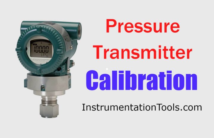
This article provides step-by-step Procedure for Pressure Transmitter Calibration and Ranging, LRV and URV configuration of transmitter.

Pressure Transmitter Details :

  • Rosemount Make, 3051 series
  • 3051T- Guage & absolute pressure (models) 0.3 to 10000psi, 10.3 mbar to 689 bar
  • 3051C, DP guage & absolute (models) 0.1 to H2o to 4000psi, 0.25 mbar to 276 bar
  • Power supply range is 12VDC to 32VDC.

Pressure Transmitter Calibration Procedure

Main Steps to be Followed :

First step to be followed is proper permit should be taken and ensure the interlocks should be by passed as well as MOS (Maintenance override to be put ON condition in DCS) for the particular tag.

Use Tool box meeting & proper PPE’S .

Required tools and suitable fittings (Such as connector and union) for calibration.

Multimeter, HART communicator, Calibrator ( Pressure range should be greater than the transmitter)

For higher range use hydraulic pressure calibrators and for low ranges use low range calibrator.

Calibration Procedure

  1. First isolate the main process isolation valve.
  2. De-pressurize the pressure transmitter by opening the vent valve
  3. Isolate the manifold valve and open the vent plug.
  4. Fix proper instrument fitting ( for eg:1/4”npt fitting)
  5. Connect the calibrator fitting in to the vent plug entry of manifold valve.
  6. The vent valve should be opened.
  7. The HART communicator cable should be placed as per transmitter wiring diagram.
  8. Apply pressure as per the range given in the transmitter or check with the HART communicator.
  9. Check the transmitter reading by applying pressure for 25%, 50%, 75%, and span range.
  10. If the transmitter needs to be calibrated use the HART communicator for calibration purpose.
  11. Zero & span trims can be done by using HART communicator.
  12. After calibration checking remove the pressure calibrator from the transmitter and flush the line.
  13. So that hydraulic oil or water will not be inside the transmitter.
  14. Close the vent plug.
  15. Isolate the vent valve and open the main isolation valve.
  16. Open the manifold isolation valve slowly, if u open fast sudden pressure may damage the transmitter diaphragm.
  17. After completion of the calibration ensure the transmitter is reading showing properly.
  18. Then enter the reading in calibration  report format.
  19. Check the reading in DCS also.
  20. Close the work permit from field operator and shift Engineer.

Articles You May Like :

Pressure Transmitter Manifolds

Differential Pressure Transmitters

Displacer Level Transmitter Calibration
4–20 mA Process Control Loops

HART Communication Guide

Don't Miss Our Updates
Be the first to get exclusive content straight to your email.
We promise not to spam you. You can unsubscribe at any time.
Invalid email address
You've successfully subscribed !
Differential Pressure Sensors Calibration Procedure
Common Mistakes to Avoid When Using Dead Weight Tester
H & B Gas Analyzer Principle and Calibration Procedure
Helix and Spiral Tubes – Pressure Sensor
Pressure Sensor Specifications
Share This Article
Facebook Whatsapp Whatsapp LinkedIn Copy Link
Share
Leave a Comment

Leave a Reply Cancel reply

Your email address will not be published. Required fields are marked *

Stay Connected

128.3kFollowersLike
69.1kFollowersFollow
208kSubscribersSubscribe
38kFollowersFollow

Categories

Recent Comments

  • Kamli on Top Free PLC Software
  • Guifty Shimica on Top Non-PLC Certification Courses for Automation Professionals
  • Guifty Shimica on Top Non-PLC Certification Courses for Automation Professionals
  • MIHARITSOA Aina Sitraka on Top Non-PLC Certification Courses for Automation Professionals

Related Articles

ORP-sensor-calibration

Oxidation-Reduction Potential (ORP) Sensor Calibration Procedure

bourdon-tube-pressure-gauge-working-animation

Working Principle of Pressure Gauge

Multiphase Flow Meter Calibration Procedure

Multiphase Flow Meter Calibration Procedure

Instrument Protection Methods: Seals

Difference between Absolute, Gauge and Differential Pressure Transmitters

Difference between Absolute, Gauge and Differential Pressure Transmitters

Diaphragm Seal Transmitters Errors

Diaphragm Seal Transmitters Errors

Differential Pressure Switch Principle

Differential Pressure Switch Principle

Instrument Calibration Lab Exercise

Instrument Calibration Lab Exercise

More Articles

Thermocouple Law of Intermediate Metals

Thermocouples Law of Intermediate Metals

Configuration of Siemens VFD Using TIA Portal

Configuration of Siemens VFD Using TIA Portal Start drive

PLC Pump Control

PLC Pump Control: 10 seconds ON & 20 seconds OFF

half-wave-voltage-doubler-using-diodes

Half Wave Voltage Doubler using Diodes

Pressure Transmitter

Pressure Transmitter Animation

Analog Electronics Objective Questions

Analog Electronics Objective Questions – Set 4

Difference between Charge and Mass

Difference between Charge and Mass

pH Analyzers Questions and Answers

Combination Electrode Questions & Answers

Follow US
All rights reserved. Reproduction in whole or in part without written permission is prohibited.
Welcome Back!

Sign in to your account

Username or Email Address
Password

Lost your password?